SI-F130 Manual(EN)_jpg_ Rev1.pdf - 第19页
RT Axis Origin Position Set up HLF-10201-01 RT A xis Origin Position Setup SHEET 2/5 2 Install a no zzle jig (AF06040) to the turret No.7. 1. Click the Jog Move button in the mov e mode. 2. Press the cursor k ey on the l…
RT Axis Origin Position Setup
HLF-10201-01
RT Axis Origin Position Setup
SHEET
1/5
RT Axis Origin Position Setup
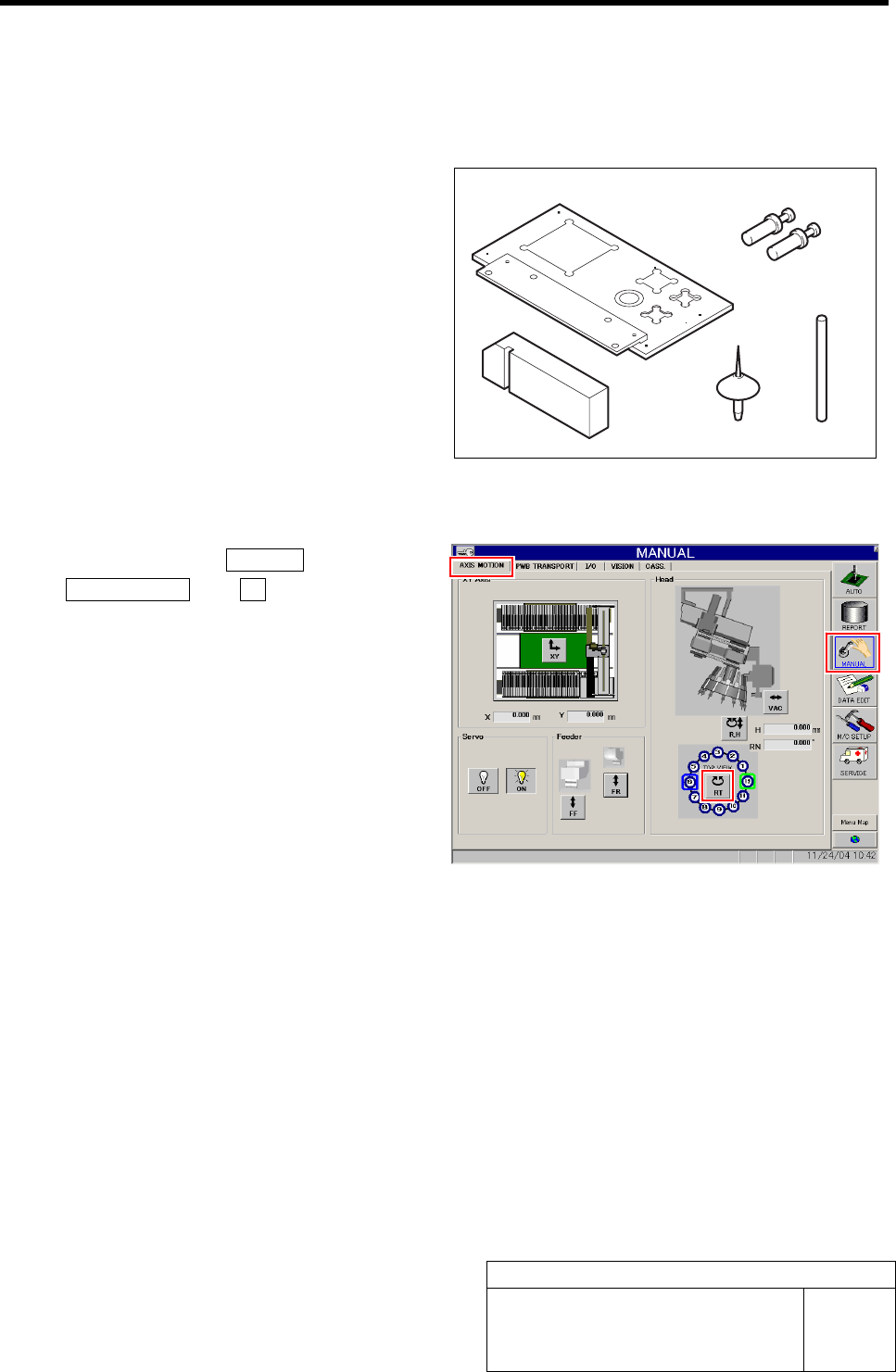
[Necessary jigs]
A Calibration plate jig
B Jig positioning pin
C Nozzle jig (AF06040)
D RT jig shaft
E RT jig block
[Procedure]
1 Click in an order of MANUAL menuÎ
AXIS MOTION tabÎRT button.
Turret RT Axis screen is displayed.
A
B
E
C D
RT Axis Origin Position Setup
HLF-10201-01
RT Axis Origin Position Setup
SHEET
2/5
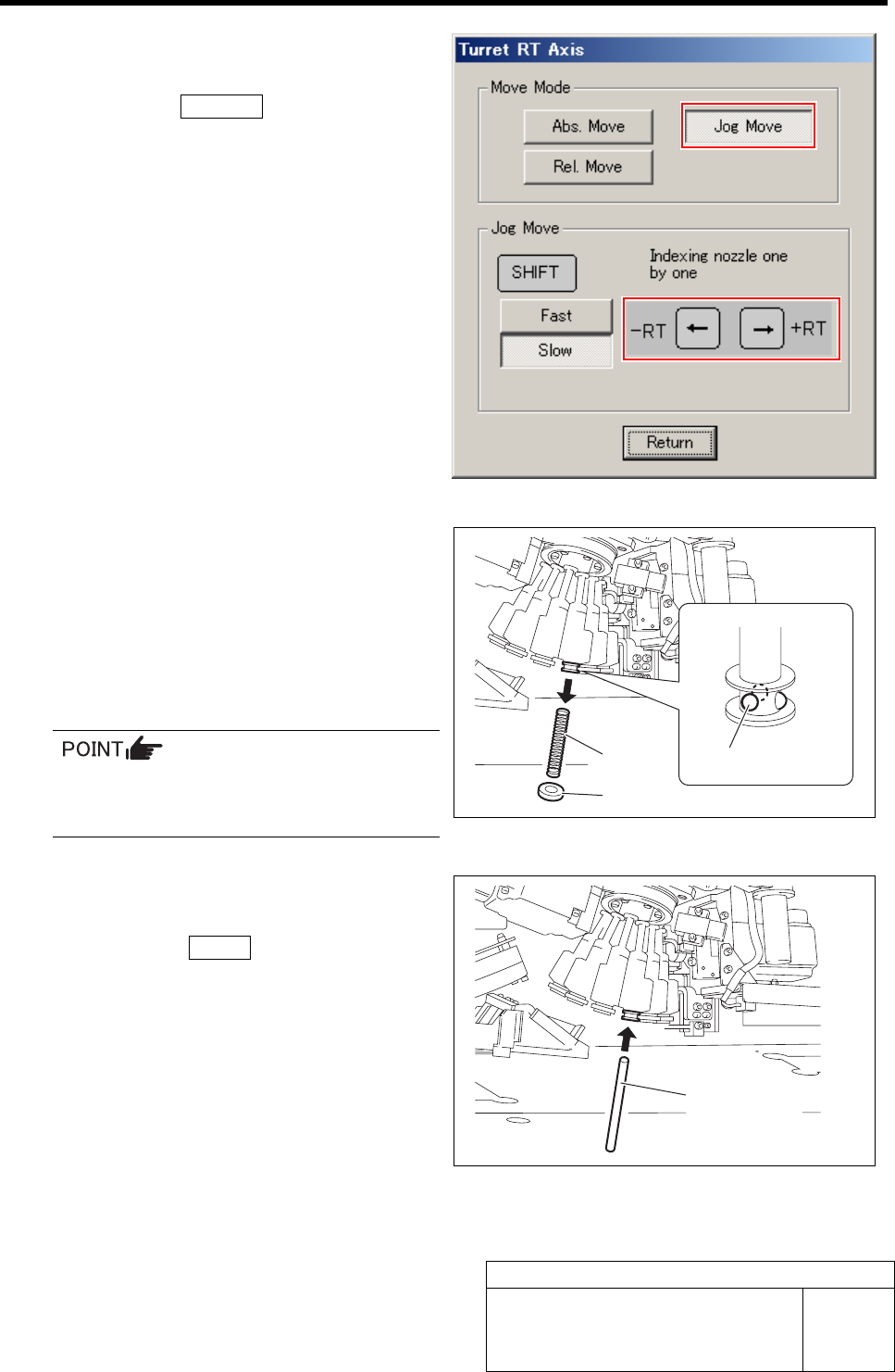
2 Install a nozzle jig (AF06040) to the turret
No.7.
1. Click the Jog Move button in the move
mode.
2. Press the cursor key on the left and
right to jog move the turret No.7 to-
ward you.
3. Slowly insert the nozzle jig (AF06040)
into the inner shaft of the turret No.7
while turning the nozzle.
4. Check that the nozzle is not drawn out
by pulling the nozzle downward.
3 Install the RT jig shaft to the turret No.1.
1. Press the cursor key on the left and
right to jog move the turret No.1 to-
ward you.
2. Remove in an order of O-ring, steel
balls (3 pieces) and spring from the
inner shaft of the turret No.1.
Because the steel balls are very small,
temporarily store them with care not to
lose.
3. Insert the RT jig shaft into the inner
shaft of the turret No.1.
4. Click the Return button to close the
Turret RT Axis screen.
O-ring
Spring
Steel ball
RT jig shaft
RT Axis Origin Position Setup
HLF-10201-01
RT Axis Origin Position Setup
SHEET
3/5
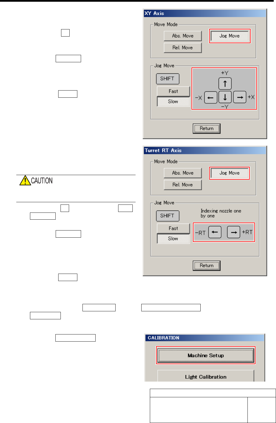
4 Move the head unit onto the calibration plate
jig by manual operation.
1. Press the XY button for the AXIS
MOTION screen.
XY Axis screen is displayed.
2. Click the Jog Move button in the move
mode.
3. Press the cursor key to jog move the
head unit onto the calibration plate jig.
4. Click the Return button to close the
XY Axis screen.
5 Move the jig shaft placed into the turret No.1
to the placement position by jog moving the
RT axis.
Be careful so that the RT jig shaft does not
collide the camera plate.
1. Click the RT button on the AXIS
MOTION screen.
Turret RT Axis screen is displayed.
2. Click the Jog Move button in the move
mode.
3. Press the left and right cursor keys to
move the jig shaft to the placement
position.
4. Click the Return button to close the
Turret RT Axis screen.
6 Display RT Axis Home screen.
1. Click in an order of M/C SETUP menu Î M/C MAINTENANCE tabÎ
Calibration button.
CALIBRATION screen is displayed.
2. Click the Machine Setup button on the
CALIBRATION screen.
Machine Setup screen is displayed.