SI-F130 Manual(EN)_jpg_ Rev1.pdf - 第161页
Adjustment of Bulk Unit Position HLF-10424-01 Adjustment of Bulk Unit Position SHEET 2/2 3 Raise and lower the bulk ca ssette jig pin to adjust it to a position where it can be easily inserted into the nozzle hol e of th…
Adjustment of Bulk Unit Position
HLF-10424-01
Adjustment of Bulk Unit Position
SHEET
1/2
Adjustment of Bulk Unit Position
[Necessary jigs]
• Bulk cassette jig
[Procedure]
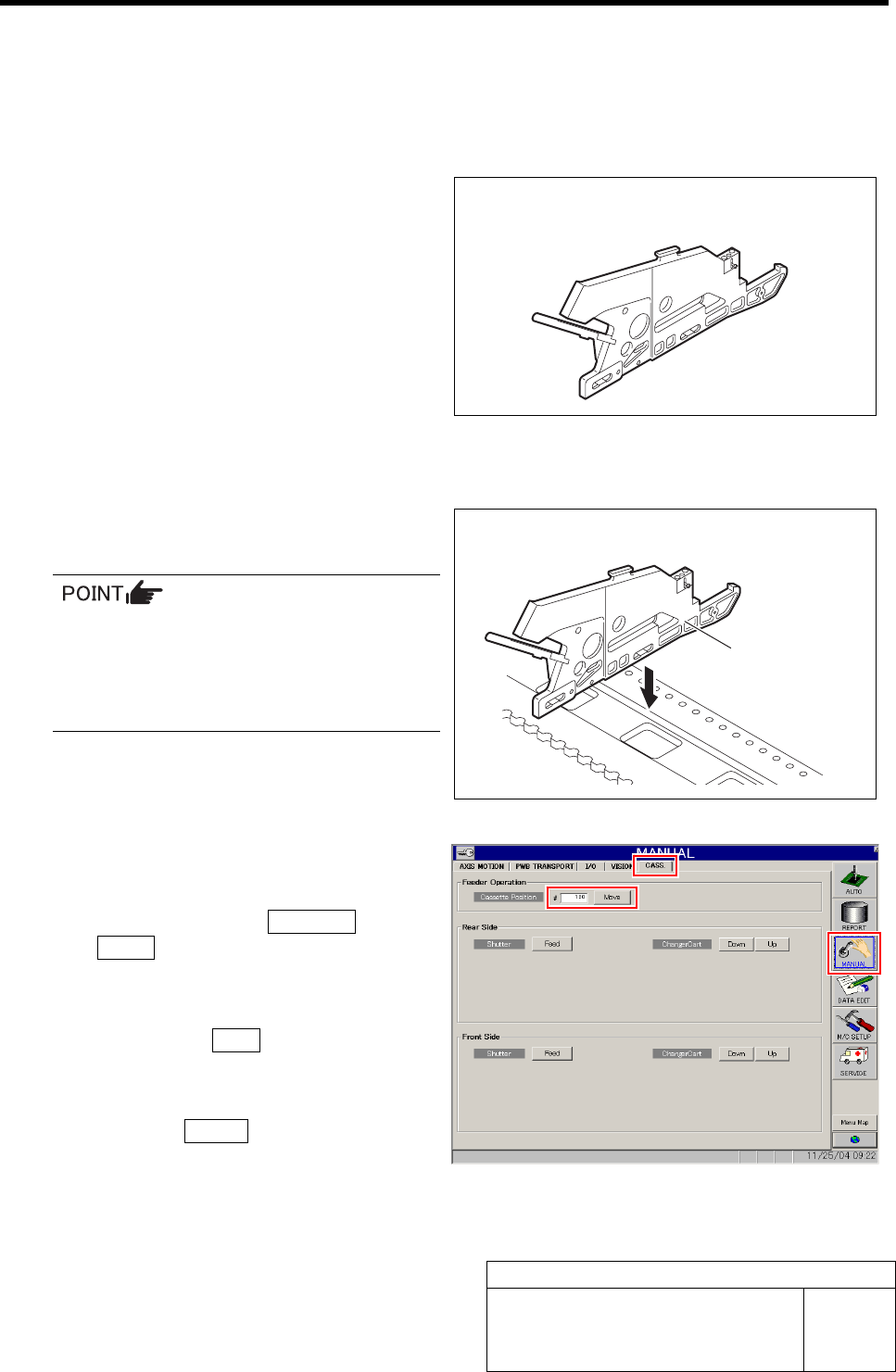
1 Set the bulk cassette jig at the position of
No.20 on the cassette table.
• There shall be no gap between the bulk
cassette jig and the cassette table.
• Set at the same jig position (front side
No.20) as set in the “Adjustment FF/FR
Axis Feed Roller X-Direction Position”.
2 Move the XY Axis to the position of cassette
No.20.
1. Click in an order of MANUAL menuÎ
CASS. tab.
Cassette operation screen is displayed.
2. Input “120” into the Cassette Position,
and click the Move button.
“Press [START] button to start Move” is dis-
played on the message screen.
3. Press the START button on the opera-
tion panel.
XY Axis moves to the position of cassette No.20.
Bulk cassette jig
Bulk cassette jig
Adjustment of Bulk Unit Position
HLF-10424-01
Adjustment of Bulk Unit Position
SHEET
2/2
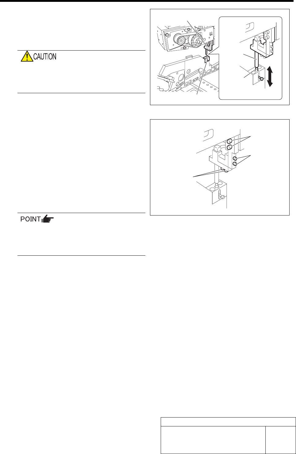
3 Raise and lower the bulk cassette jig pin to
adjust it to a position where it can be easily
inserted into the nozzle hole of the air supply
unit block.
Do not move the X and Y axes.
If the X or Y axis is moved, the positional
relation with the pickup point becomes out of
adjustment.
1. Loosen the order adjustment screws
(2-M3) to adjust to a position where
the pin can be smoothly inserted into
the nozzle hole.
2. Fasten the order adjustment screws.
3. Loosen the height adjustment screws
(2-M3) to align the nozzle end with the
upper face of the bulk cassette jig pin
unit.
4. Fasten the height adjustment screws.
If the nozzle position is not aligned even
when the above procedure is performed,
loosen the air supply block attachment
bolts (2-M4) to adjust the nozzle position.
Air supply unit block
Bulk cassette jig pin unit
Nozzle
Pin
Attachment bolt
(2-M4)
Height adjust-
ment screw
(2-M3)
Order adjustment
screw (2-M3)

Blow Flow rate Setup
HLF-10425-01
Blow Flow rate Setup
SHEET
1/4
Blow Flow rate Setup
This section describes a procedure to set up blow flow rate.
[Necessary jig]
• Flowmeter
• Flow rate measuring nozzle jig
• Nozzle jig (AF12080): 12 pieces
[Procedure]
1 Prepare flowmeter.
1. Turn on power for the flowmeter and warm up for one minute.
2. Check that the displayed value on the flowmeter is “0±0.009”.
When the displayed value on the flowmeter is not “0±0.009”, adjust the zero point in the fol-
lowing procedure.
1) Close the IN-OUT part on the flowmeter with tape to warm up for 30 minutes.
2) Carefully remove the serial number seal on the upper of the flowmeter main body until the
volume is seen.
3) Slowly turn the zero adjustment volume (remote from the signal connector) with precision
screw driver to adjust zero point.
4) After zero point adjustment, return the serial number seal to the previous state, and remove
the tape closing the IN-OUT part.
2 Turn off the VACUUM breaker.
1. Loosen 2 screws to remove the lower
panel on the front of the unit.
2. Turn off the VACUUM breaker on the
PC unit part.
VACUUM breaker
Flowmeter
Flow rate measuring
nozzle jig
Nozzle jig (AF12080)