编带机说明书-含图纸tm401.pdf - 第11页
Operator Requirements D292104.2.fm vii Operator Requir e ments The guidelines provided in the following p ages are intended to educate the user about how to operate the TM-401 safely . They cont ain important info rmatio…
Intended Use D292104.2.fm vi
Misuse
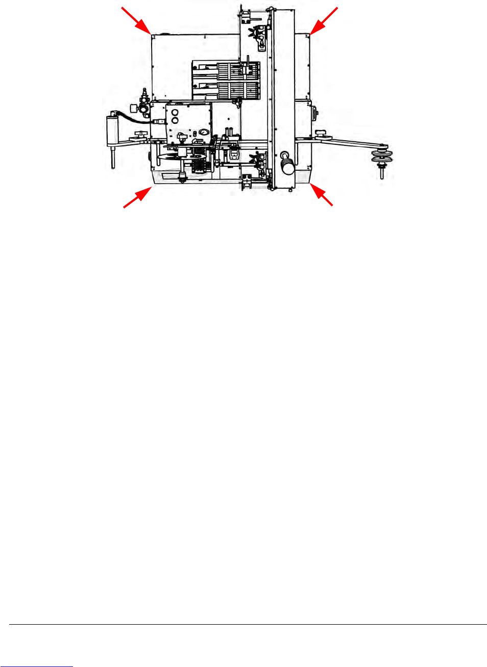
The TM-401 weighs approximately 217 lbs. (98.5 kg.) and requires four people to safely carry it.
Operators are cautioned to follow the instructions and illustrations for safely transporting the TM-
401. Failure to do so could result in injury or damage to the machine.
Installation instructions clearly state that the TM-401 should only be installed or operated on a
level surface to prevent toppling.
The user is protected from moving parts and exposure to objects being ejected under pressure
by 16 standard wire gauge sheet metal and 3/8 inch clear, polycarbonate enclosures. Door sen-
sors ensure operation automatically stops if the enclosure doors are opened. No attempt should
be made to remove these enclosures or to block, disable or override the door sensors.
The enclosure doors may be left open during basic set-up procedures such as positioning the
pick head at place or pick locations. If the enclosure doors are left open during setup the TM-401
automatically reduces the speed of the pick head to a fraction of its normal operating speed to
prevent operator injury due to collision, etc.
The user is protected from the TM-401’s heat sealer by a metal guard. Operators are cautioned
not to touch the heat seal guard or to try to reach underneath the guard while the heat sealer is in
operation.
The TM-401 air supply should be adjusted to operate at a maximum working pressure not
exceeding 7.6 bar (110 psi). The maximum permissible source pressure should not exceed 9 bar
(130 psi). Failure to set the air pressure within these limits could result in a failure in the pneu-
matic system which could lead to injury.
Lift Points
Downloaded from www.Manualslib.com manuals search engine
Operator Requirements D292104.2.fm vii
Operator Requirements
The guidelines provided in the following pages are intended to educate the user about how to
operate the TM-401 safely. They contain important information on avoiding potential hazards to
the operator and to the equipment. Only personnel who have thoroughly reviewed and under-
stand the TM-401 User’s Guide and are aware of the possible hazards should operate or perform
maintenance on the TM-401.
Operators and maintenance personnel are advised not to wear loose fitting clothing or jewelry
when operating or maintaining the TM-401. Protective eye wear should be worn when loading,
operating or maintaining the TM-401.
Caution: Users should always wear protective eye wear when loading,
operating or maintaining the TM-401.
Safe operation of the TM-401 does not require gloves of any type, however some component
manufacturers may recommend gloves be worn when placing parts in tape. Consult the compo-
nent manufacturer for specific placement instructions. Ear protection is not necessary during nor-
mal operation.
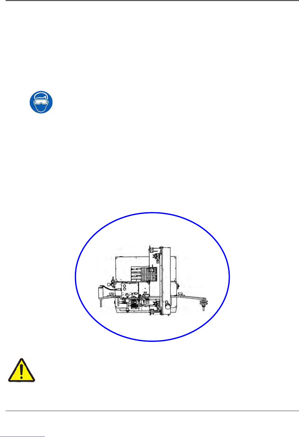
When running the TM-401, the operator should stand or sit in front of the touch screen to assure
easy access to all controls and the Power/Emergency Stop Button. This position allows the oper-
ator to view all parts of the TM-401 while it is in operation. When loading the TM-401 Manual
Tube Input Device (MTID or changing Taper reels, the operator may also need to access the side
and back of the machine
Caution!
The TM-401 should never be operated while under the influence of alcohol or drugs.
V-TEK® Incorporated takes no responsibility for the safety of TM-401 if it is used for
any purpose other than the intended purpose as specified in this User’s Guide.
Work Area
Downloaded from www.Manualslib.com manuals search engine
Safety Features D292104.2.fm viii
Safety Features
Main Power Switch
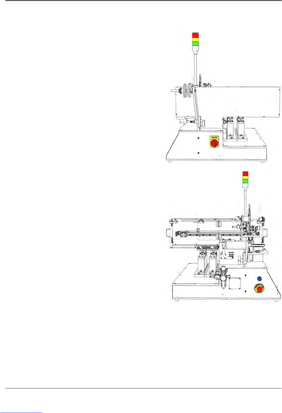
The Main Power Switch is located on the right side
of the machine. Turning the switch to the right
turns power ON. Turning the switch back to the left
turns the power OFF.
When the Main Switch is in the OFF position, it
exposes a lockout-tagout hole. The switch can be
locked by inserting a lock through the hole. The
switch on the right is pictured in the OFF position.
Emergency Stop Switch
There is one Emergency Stop Switch on the TM-
401. It is located on the left side of the machine
below the Take-up Arm. When an emergency stop
switch is triggered, all motion will be halted and the
machine will require a reset before operation can
continue.
The emergency stop control circuit removes elec-
trical power to all motors, moving parts, heat
sources, pneumatics, and energy storing devices.
This includes the stepper motor drive, stepper
motors, the servo motor drive, servo motors, drive
circuits, the main control board, the heat sealer
and all pneumatics. The only devices that remain
powered are the inspection module cameras, the
enclosure lights, the sensors, and the HMI.
Reset Button
The TM-401’s blue Reset button is located on the left side of the machine above the Emergency
Stop Switch. When the machine is powered up, it is automatically placed into an emergency stop
state to prevent the motors from moving until the operator is ready to begin operating the
machine. The error state is cleared by pressing the Reset button on the front of the machine.
Downloaded from www.Manualslib.com manuals search engine