编带机说明书-含图纸tm401.pdf - 第41页
D292104.5a.fm Tube Feeder. Chapter 2: TM-401 Overview 2-11 T ube F eeder . A. Pick Area B. On/Of f, Amplitude and Frequency Controls C. Feeder D. Y Axis Clamping Bolt s E. Slotted Plate Note: T ooling for the T ube Feede…
2-10 TM-401 User’s Guide
Pick & Place Assembly D292104.5a.fm
Pick & Place Assembly
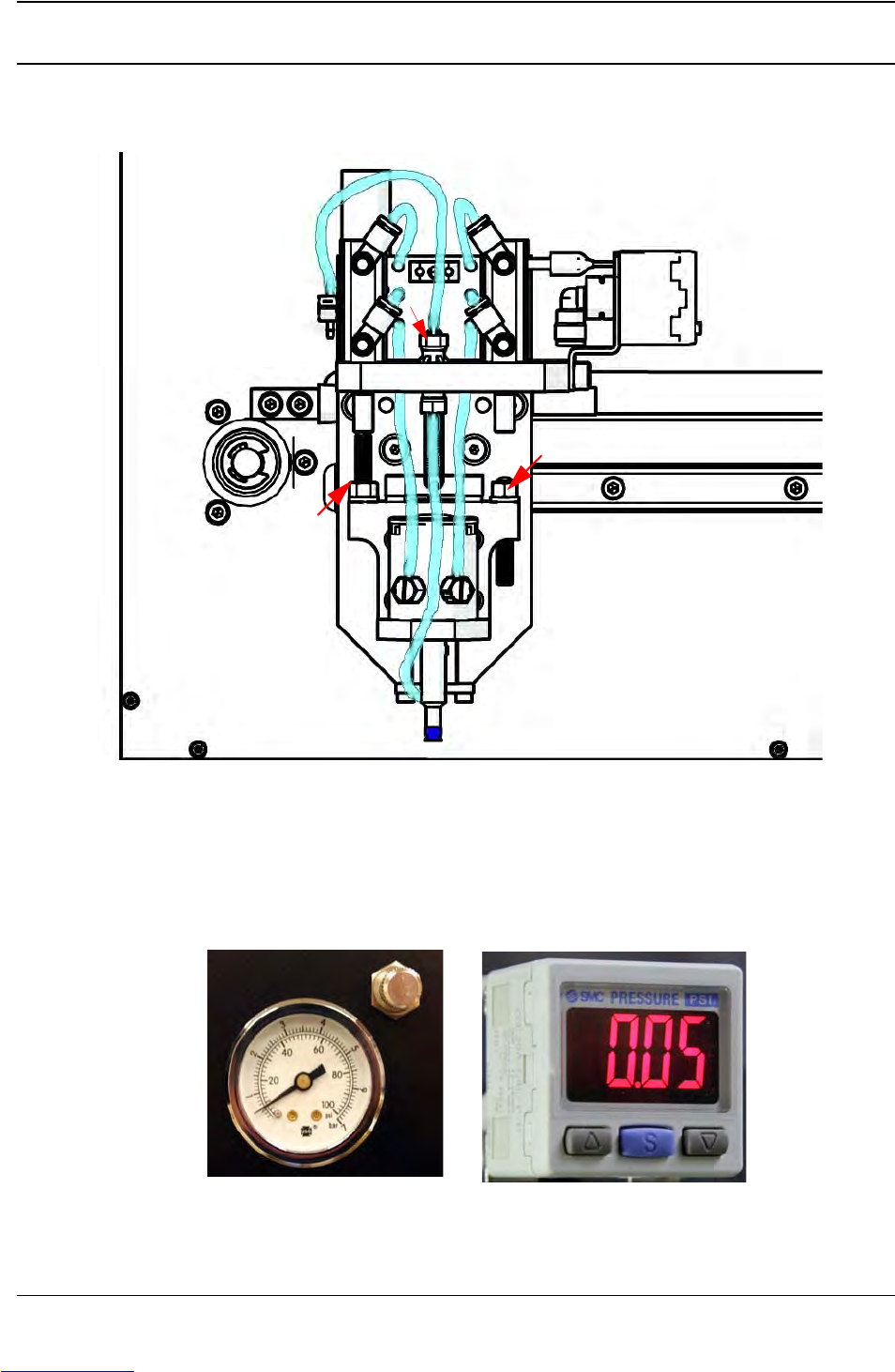
Pick & Place Head
A. Nozzle D. Pick Actuator Adjustment Screw
B. Nozzle Vacuum Sensor E. Place Actuator Adjustment Screw
C. Nozzle Vacuum Filter
Pick & Place Controls
A. Blow-off Air Pressure Gauge & Control B. Nozzle Vacuum Sensor
A
B
D
E
C
AB
Downloaded from www.Manualslib.com manuals search engine
D292104.5a.fm Tube Feeder.
Chapter 2: TM-401 Overview 2-11
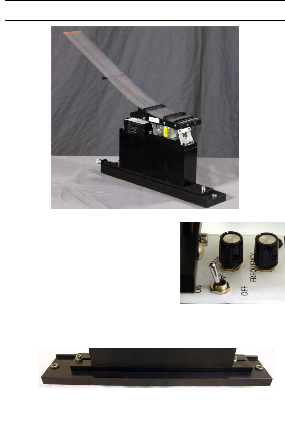
Tube Feeder.
A. Pick Area
B. On/Off, Amplitude and Frequency Controls
C. Feeder
D. Y Axis Clamping Bolts
E. Slotted Plate
Note: Tooling for the Tube Feeder will vary to fit
part parameters. The TM-401 can be equipped
with one or two Tube Feeders, as desired.
.
A
B
C
D
D
E
B
Adjust Feeder position on Slotted Plate
D
D
E
Downloaded from www.Manualslib.com manuals search engine
2-12 TM-401 User’s Guide
2D Vision System D292104.5a.fm
2D Vision System
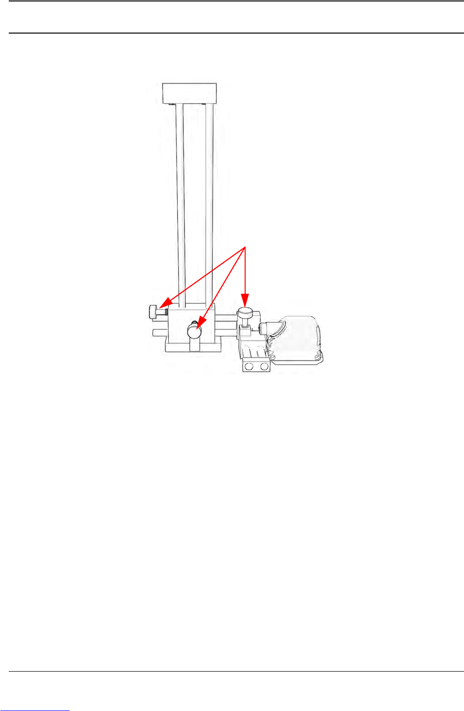
The Keyence IV Vision system consists of the following components shown below.
A. Adjustable Mounting Bracket F. Status LED
B. Position Adjustment Knobs G. Ethernet Traffic Indicator
C. Power & I/O Connector H. Keyence IV-G Camera
D. Ethernet Connector I. Lens Cover/Focus Ring
E. M12 Ethernet Cable (not shown)
Note: For advanced Vision configuration, a computer is required. This can be provided by
the user or purchased as an option from V-TEK, Inc. System requirements for the vision
computer follow:
• Operating system: Microsoft® Windows 7
TM
(32 or 64 bit)
• 128 MB RAM
• 1024 x 768 (96 DPI) or 1280 x 1024 (120 DPI display
• Ethernet port
A
B
C
Downloaded from www.Manualslib.com manuals search engine