编带机说明书-含图纸tm401.pdf - 第143页
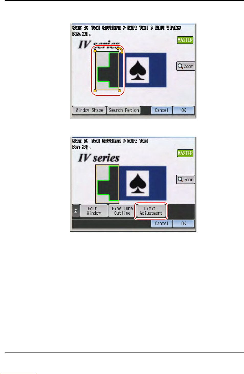
D292104.16.fm Configure Inspection Chapter 5: Setup 5- 41 4. Set the position, size, and the angle of t he tool window . The detected outline will be displayed in green. T ouch OK . 5. T ouch the Limit Adjustment button.…
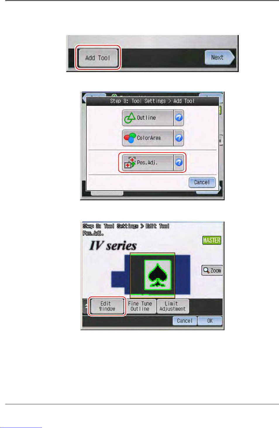
D292104.16.fm Configure Inspection
Chapter 5: Setup 5- 41
4. Set the position, size, and the angle of the tool window. The detected outline will be
displayed in green. Touch OK.
5. Touch the Limit Adjustment button.
Step 2:
Vision
Setup
CONFIGURE
MONITOR
Downloaded from www.Manualslib.com manuals search engine
5-42 TM-403 User’s Guide
Configure Inspection D292104.16.fm
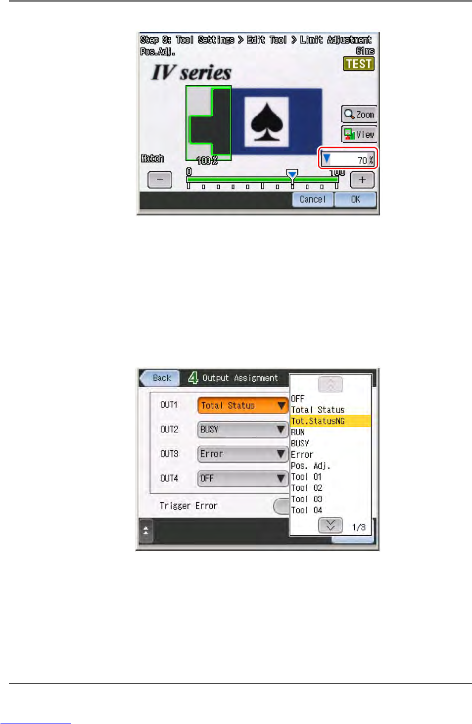
6. Set the threshold to judge OK and NG.
7. After the setting is completed, touch OK. The display will return to the main screen
for Position Adjustment tool.
8. Touch OK again, then touch Next to proceed to “STEP4”.
Setup Output
1. Touch the output line to assign the output function.
Step 2:
Vision
Setup
CONFIGURE
MONITOR
Downloaded from www.Manualslib.com manuals search engine