编带机说明书-含图纸tm401.pdf - 第37页
D292104.5a.fm Controls, Connection s & Labeling Chapter 2: TM-401 Overview 2-7 Main P o wer Switch The Main Power Switch is located on the right side of the machine behind the Carrier T ape Arm on the lower sheet met…
2-6 TM-401 User’s Guide
Controls, Connections & Labeling D292104.5a.fm
Controls, Connections & Labeling
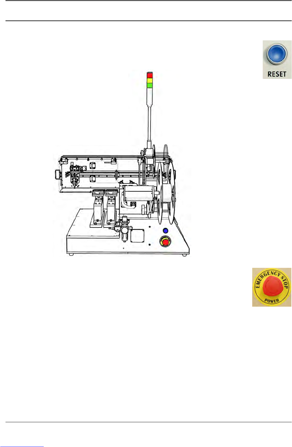
Reset Button
The TM-401’s blue Reset Button is located on the left side of the machine
below the Take-up Arm. (pictured below)
Emergency Stop Switch
The Emergency Stop Switch is located on the left side of the machine below
the blue Reset Button. (pictured above)
Downloaded from www.Manualslib.com manuals search engine
D292104.5a.fm Controls, Connections & Labeling
Chapter 2: TM-401 Overview 2-7
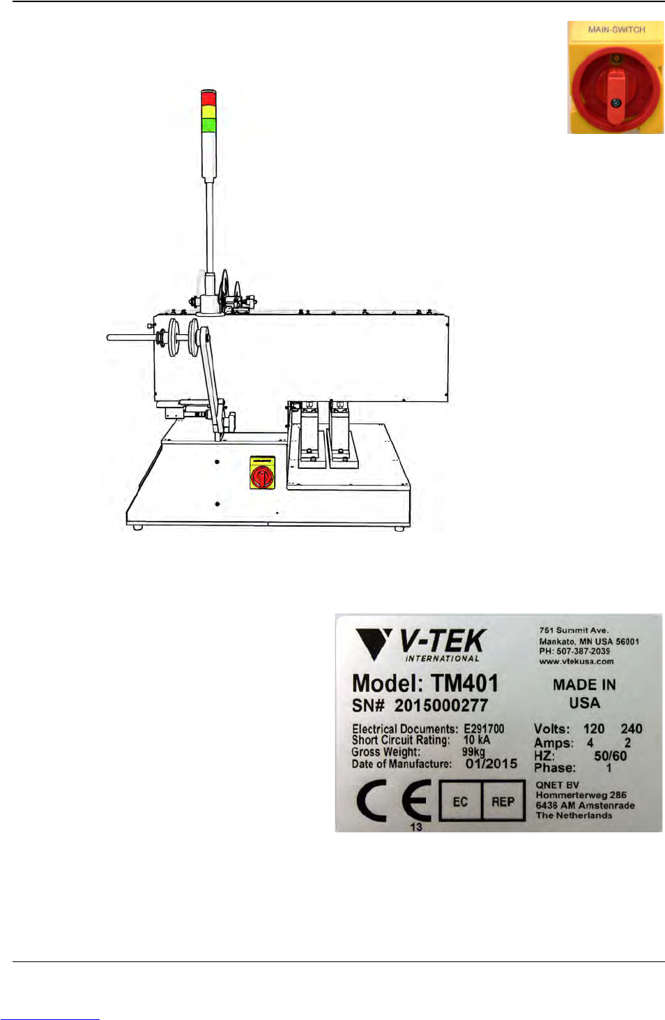
Main Power Switch
The Main Power Switch is located on the right side of the machine behind the
Carrier Tape Arm on the lower sheet metal enclosure.
Serial Plate
This is an example of the Serial Plate which is
permanently affixed to the back of the TM-
401. It includes basic machine information
such as machine weight, power usage and
short circuit rating. The Serial Plate also docu-
ments machine specific information such as
the machine’s model name, date of manufac-
ture and unique serial number
Downloaded from www.Manualslib.com manuals search engine
2-8 TM-401 User’s Guide
The Taper D292104.5a.fm
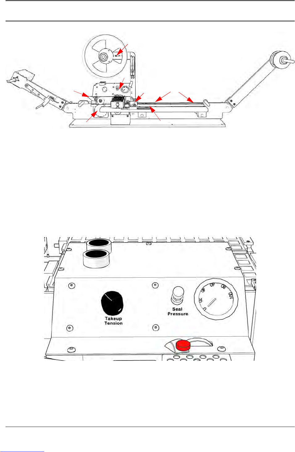
The Taper
A. Take-up Arm H. Sensor Amplifiers
B. Take-up Guide I. Cover Tape Guide
C. Drive Sprocket J. Heat/PSA Sealer
D. Idler Wheel K. Tape Jam Sensor
E. Sealer Controls & Pressure Gauge L. Adjustable Width Track
F. Cover Tape Reel M. Carrier Tape Guide
G. Low Cover Sensor N. Carrier Tape Arm
Taper Controls
A. Pick Head Jog Buttons
B. Take-up Tension Control
C. Sealer Air Pressure Control
D. Sealer Air Pressure Gauge
E. Inside Seal Position Lock/Adjust
A
C
B
E
F
H
I
L
N
G
J
D
M
K
B
A
C
D
E
Downloaded from www.Manualslib.com manuals search engine