编带机说明书-含图纸tm401.pdf - 第31页
Cha pter 2: Machine Ov er vie w Content s Front View . . . . . . . . . . . . . . . . . . . . . . . . . . . . . . . . . . . . . . . . . . . . . . . . . . . . 2-2 Right Side View . . . . . . . . . . . . . . . . . . . . . .…
1-10 TM-401 User’s Guide
Assembling the TM-401 D292104.4.fm
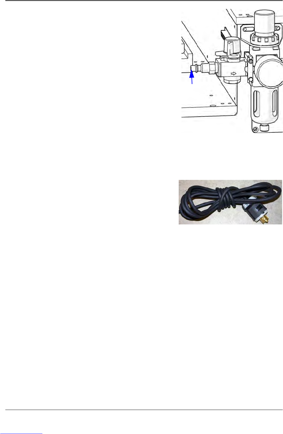
5. Connect the Air Supply.
a. Attach the air supply line to the air regula-
tor, then connect it to the air supply.
b. Set the regulator to 85 psi, if necessary. It
can be adjusted by lifting the adjustment knob
and turning it. Once it reads 85 psi, push the
knob back in to lock it into place
NOTE: It is recommended that the air hose be
routed overhead or underground. If it must be
routed over the floor, cover the hose with rub-
ber ramps.
6. Inspect the TM-401.
a. Inspect the fully assembled TM-401, verifying that all twist ties have been removed
and all cables are secure.
b. Connect the power cord to the power
receptacle on the back of the TM-401, then
connect the other end to a 120/240 Volt single
phase power supply
Note: It is recommended that the power cord
be routed overhead or underground. If it must
be routed over the floor, cover the cords with
rubber ramps.
Protective earth grounding of the TM-401 is included in the manufacture of the TM-401 at
V-TEK. The TM-401 is fully tested before shipping. No further grounding or testing is
required during re-assembly and installation.
The TM-401 is ready to power up. Follow the instructions in Chapter 3: Machine Setup to setup
the machine for operation.
Air Line
Connect
Here
Downloaded from www.Manualslib.com manuals search engine

Chapter 2: Machine Overview
Contents
Front View . . . . . . . . . . . . . . . . . . . . . . . . . . . . . . . . . . . . . . . . . . . . . . . . . . . . 2-2
Right Side View . . . . . . . . . . . . . . . . . . . . . . . . . . . . . . . . . . . . . . . . . . . . . . . . 2-3
Left Side View . . . . . . . . . . . . . . . . . . . . . . . . . . . . . . . . . . . . . . . . . . . . . . . . . 2-4
Back View . . . . . . . . . . . . . . . . . . . . . . . . . . . . . . . . . . . . . . . . . . . . . . . . . . . . 2-5
Controls, Connections & Labeling . . . . . . . . . . . . . . . . . . . . . . . . . . . . . . . . . . 2-6
The Taper. . . . . . . . . . . . . . . . . . . . . . . . . . . . . . . . . . . . . . . . . . . . . . . . . . . . . 2-8
Pick & Place Assembly . . . . . . . . . . . . . . . . . . . . . . . . . . . . . . . . . . . . . . . . . . 2-10
Tube Feeder. . . . . . . . . . . . . . . . . . . . . . . . . . . . . . . . . . . . . . . . . . . . . . . . . . . 2-11
2D Vision System. . . . . . . . . . . . . . . . . . . . . . . . . . . . . . . . . . . . . . . . . . . . . . . 2-12
Downloaded from www.Manualslib.com manuals search engine
2-2 TM-401 User’s Guide
Front View D292104.5a.fm
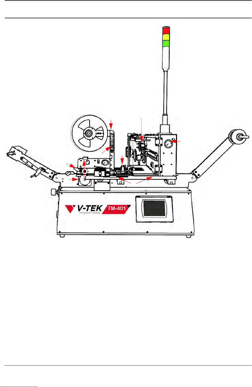
Front View
A. Take-up Arm H. Vision System
B. Air Regulator I. Taper Track
C. Idler Wheel J. Pick & Place Head Assembly & Bridge
D. Drive Sprocket K. Touch Screen HMI
E. Cover Tape Arm L. Tower Light
F. Heat/PSA Sealer M. Blow-off Air Pressure Gauge & Control
G. Sensor Amplifiers N. Carrier Tape Arm
A
B
D
F
K
J
L
M
N
I
G
C
H
E
Downloaded from www.Manualslib.com manuals search engine