编带机说明书-含图纸tm401.pdf - 第25页
D292104.4.fm Unpacking the TM-401 Chapter 1: Assembly & Installation 1- 5 Unpacking the TM-401 Prior to shipment, the TM-401 is p artially disa ssembled, th en shrink wrapped, placed in a crate, and strapped to the c…

1-4 TM-401 User’s Guide
Preparing the Work Area D292104.4.fm
When positioning the TM-401, choose an area that is not located below overhead gantries, walk-
ways or power lines to ensure objects or liquids cannot be dropped on the machine from over-
head.
Power Requirements
The TM-401 will also require access to a 85-110 PSI air pressure system and a 120/240 VAC,
50/60 Hz power supply. Locate the machine so electrical power cables can be routed away from
areas where personnel are expected to move.
Note: It is recommended that cables be routed overhead or underground. If cables must
be routed over the floor, cover them with rubber ramps.
Downloaded from www.Manualslib.com manuals search engine
D292104.4.fm Unpacking the TM-401
Chapter 1: Assembly & Installation 1- 5
Unpacking the TM-401
Prior to shipment, the TM-401 is partially disassembled, then shrink wrapped, placed in a crate,
and strapped to the crate floor. The disassembled TM-401 parts, which include the Carrier Tape
Arm, the Take-up Assembly, the Tower Light and the Spare Parts Kit, are individually bubble-
wrapped and packed around the base machine. The TM-401 crate should contain the base
machine along with the following items.
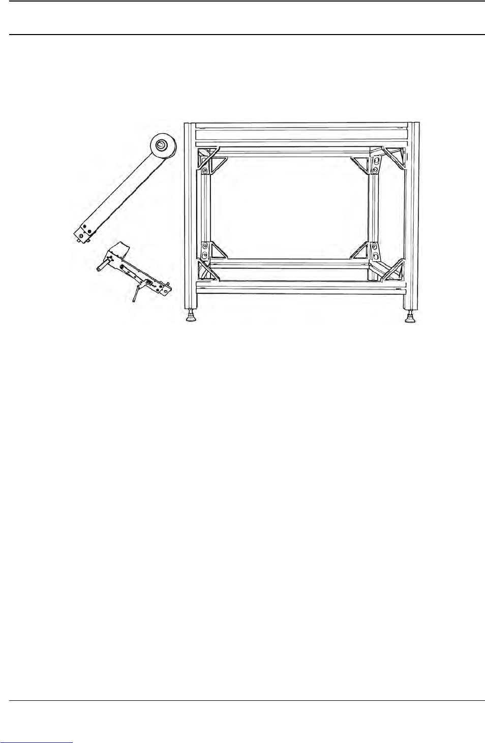
A. Carrier Tape Arm
B. 80/20 Frame (optional, shipped disassembled)
C. Take-up Arm
D. Laptop Computer (optional, not pictured)
A User’s Guide, Standard and Metric Hex Wrench Sets, and a Spare Parts Kit are also included
but not pictured above.
A
B
C
Downloaded from www.Manualslib.com manuals search engine
1-6 TM-401 User’s Guide
Assembling the TM-401 D292104.4.fm
Assembling the TM-401
Equipment Required
• Adjustable wrench (needs to fit 1 1/16” to 1 3/32” nut)
• Hex wrench set (provided with machine)
• 85-110 PSI air pressure system
Note: Read the TM-401 User’s Guide before assembling the TM-401.
Unpack the TM-401 Crate
1. Move the Crate to the Work Area. Use a fork lift to move the TM-401 crate to the pre-
pared work area. Ensure the fork is centered under the crate before lifting.
Note: Use a forklift with a minimum load capacity of 300 pounds (136 kg) and a fork
length that is a minimum of 35 inches (89 cm) so the fork fully extends beyond the crate
on the other side. The forklift should only be operated by a licensed/certified operator.
2, Unpack the Crate.
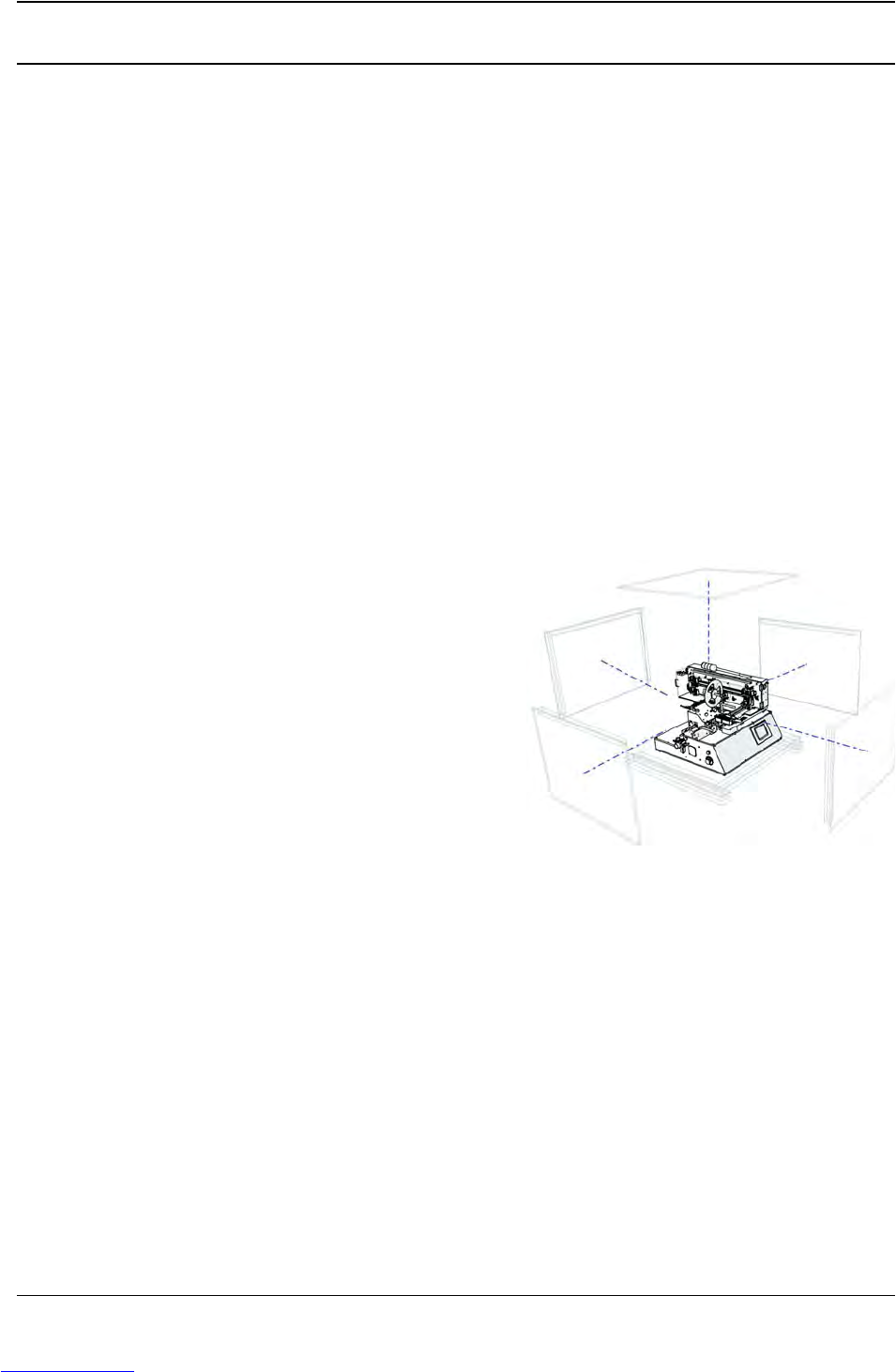
a. Remove the top and sides from the TM-
401 crate. Set aside.
b. The TM-401 is shipped partially disas-
sembled, with the Tower Light, Take-up
Arm and Carrier Tape/Feed Arm detached
and wrapped in bubble wrap. Remove the
smaller items one at a time from the crate
and place on a flat, stable surface for
assembly.
c. Remove and discard the protective wrapping from each part.
3. Remove the TM-401 from the Crate.
a. The TM-401 is bolted to the bottom of the crate for shipping. Reach below the crate to
unfasten the bolts.
Note: If the optional 80/20 Frame was purchased, follow the assembly instructions in the
80/20 Frame Exploded Views document which can be found in the Exploded Views sec-
tion at the end of this manual before proceeding.
Downloaded from www.Manualslib.com manuals search engine