编带机说明书-含图纸tm401.pdf - 第84页
4-10 TM-401 User’s Guide Taper Setup D292104.7a.fm 3. Mount the bulk carrier tape reel on the spindl e, ensuring that there is sufficient t ape for the batch to be run. The carrier tape should roll of f to the left, un w…
D292104.7a.fm Taper Setup
Chapter 4: Setup 4- 9
Ta p e r S e t u p
Loading Tape
The Taper must be loaded with carrier and cover tapes and configured for operation.
Begin by preparing the Taper, then move to the HMI to adjust settings. (Step 7)
Load Carrier Tape
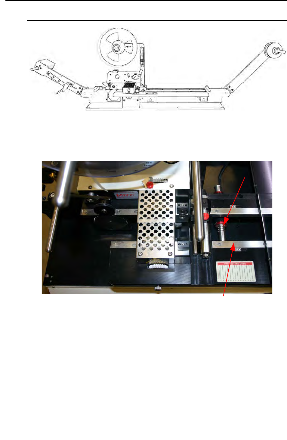
1. The outer track slides along two detent shafts that are marked with preset
positions for various tape widths. Detent stops are designed to accommodate the
following tape widths: 8mm, 12mm, 16mm, 24mm, 32mm, 44mm, 56mm, and
72mm. The track can be adjusted by sliding the outer track outward until it reaches
the correct indentation.
Check that the taper is set at the correct width for the carrier tape. If not, pull the
front track out until it clicks into the correct position.
2. Once the track is adjusted, use a strip of the carrier tape as a test to determine if
the setting is correct. The carrier tape should slide through freely, but without
excess play back and forth.
Step 5:
Load
Ta p e r
Step 5:
Setup
Ta p e r
CARRIER
TA P E
Detent Shaft
Outer Track
Downloaded from www.Manualslib.com manuals search engine
4-10 TM-401 User’s Guide
Taper Setup D292104.7a.fm
3. Mount the bulk carrier tape reel on the spindle, ensuring that there is sufficient tape
for the batch to be run.
The carrier tape should roll off to the left, unwinding from the top so it will feed right
side up into the carrier tape channel underneath the Pick Head Enclosure. The
sprocket holes of the carrier tape are on the inside for tape widths less than 32mm.
Tapes wider than 32mm have holes on both sides.
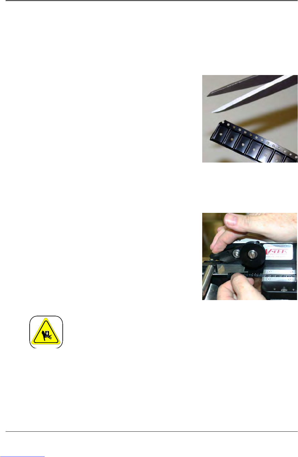
4. Trim the end of the carrier tape, cutting
between two pockets with a sharp scissors so
the edge is cleanly cut. Cut the edge of the
tape again, cutting through a sprocket hole at
a 45° angle so the tape feeds easily.
5. Guide the carrier tape under the Carrier Tape
Guide and then feed it through the carrier
tape channel under the taper.
Note: A sharp instrument, such as a pair of
tweezers may aid in guiding the carrier tape
into the loading track.
6. Continue to guide the carrier tape forward
through the loading track and the sealer until it reaches the sprocket.
7. Lift the idler wheel and place the carrier tape
onto the sprocket so that the holes engage
the teeth. Release the idler wheel so that it is
secured in place.
Mechanical Hazard!
Do not attempt to activate the sprocket while tape is being routed
through the sealer. Pinching or entrapment may occur if safety precau-
tions are not observed.
Step 5:
Setup
Ta p e r
CARRIER
TA P E
Downloaded from www.Manualslib.com manuals search engine
D292104.7a.fm Taper Setup
Chapter 4: Setup 4- 11
Load Cover Tape
1. Remove the Reel Lock mechanism and place a reel of cover tape of the correct
width to match the carrier tape on the cover tape spindle. The tape should unwind
to the right from the bottom of the reel. Ensure that there is sufficient tape for the
batch to be run. The reel should be pushed onto the holder so that it is flush with
the back.
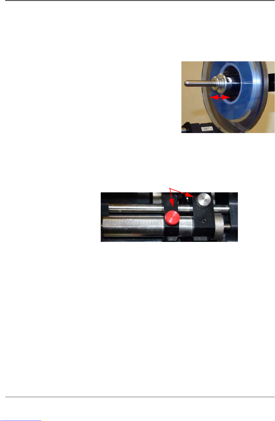
2. Replace the Reel Lock and position it so the
reel is supported and spins freely on the
spindle with little or no drag.
Note: To remove the Reel Lock mecha-
nism from the cover tape support arm, sim-
ply pull the two metal disks apart and slide
the Reel Lock off the spindle.
3. Check that the cover tape guide width is adjusted correctly for the cover tape that
will be used. Pull the cover tape down and compare it to the current setting
If the guide is set too wide or too narrow, loosen the red knob set screw and pull or
push the guide in and out until it matches the width of the cover tape with only a
slight amount of extra room..
4. If the cover tape is PSA, attach it to the carrier tape using the adhesive on the
underside of the tape.
If the cover tape is Heat Seal, use blue Permacel tape to attach the cover tape to
the carrier tape just ahead of the cover tape guide.
5. Thread both the carrier tape and cover tape through the cover tape guide sealer
assembly.
Note: A sharp instrument, such as a pair of tweezers may aid in guiding the cover
tape into the sealer.
Step 5:
Setup
Ta p e r
COVER
TA P E
Width Adjustment Knobs
Downloaded from www.Manualslib.com manuals search engine