编带机说明书-含图纸tm401.pdf - 第27页
D292104.4.fm Assembling the TM-401 Chapter 1: Assembly & Installation 1- 7 b. Moving th e TM-401 Base Machine. The machine may b e manually lif ted from the crate. The base machine weighs 217 lb . (98.5 Kg) so the t …
1-6 TM-401 User’s Guide
Assembling the TM-401 D292104.4.fm
Assembling the TM-401
Equipment Required
• Adjustable wrench (needs to fit 1 1/16” to 1 3/32” nut)
• Hex wrench set (provided with machine)
• 85-110 PSI air pressure system
Note: Read the TM-401 User’s Guide before assembling the TM-401.
Unpack the TM-401 Crate
1. Move the Crate to the Work Area. Use a fork lift to move the TM-401 crate to the pre-
pared work area. Ensure the fork is centered under the crate before lifting.
Note: Use a forklift with a minimum load capacity of 300 pounds (136 kg) and a fork
length that is a minimum of 35 inches (89 cm) so the fork fully extends beyond the crate
on the other side. The forklift should only be operated by a licensed/certified operator.
2, Unpack the Crate.
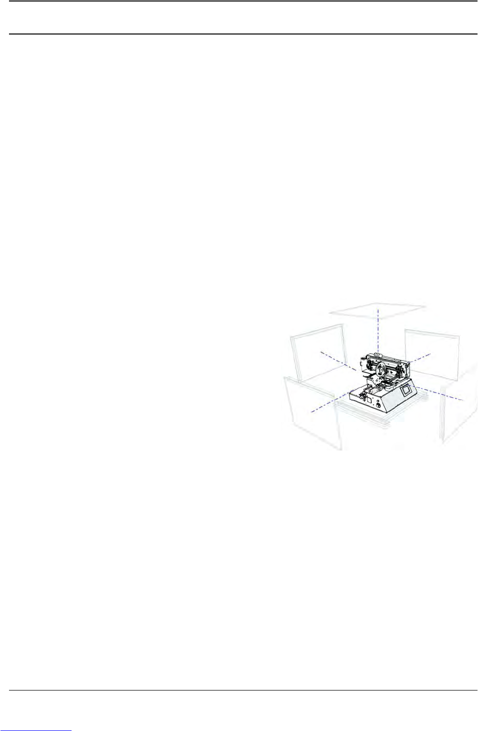
a. Remove the top and sides from the TM-
401 crate. Set aside.
b. The TM-401 is shipped partially disas-
sembled, with the Tower Light, Take-up
Arm and Carrier Tape/Feed Arm detached
and wrapped in bubble wrap. Remove the
smaller items one at a time from the crate
and place on a flat, stable surface for
assembly.
c. Remove and discard the protective wrapping from each part.
3. Remove the TM-401 from the Crate.
a. The TM-401 is bolted to the bottom of the crate for shipping. Reach below the crate to
unfasten the bolts.
Note: If the optional 80/20 Frame was purchased, follow the assembly instructions in the
80/20 Frame Exploded Views document which can be found in the Exploded Views sec-
tion at the end of this manual before proceeding.
Downloaded from www.Manualslib.com manuals search engine
D292104.4.fm Assembling the TM-401
Chapter 1: Assembly & Installation 1- 7
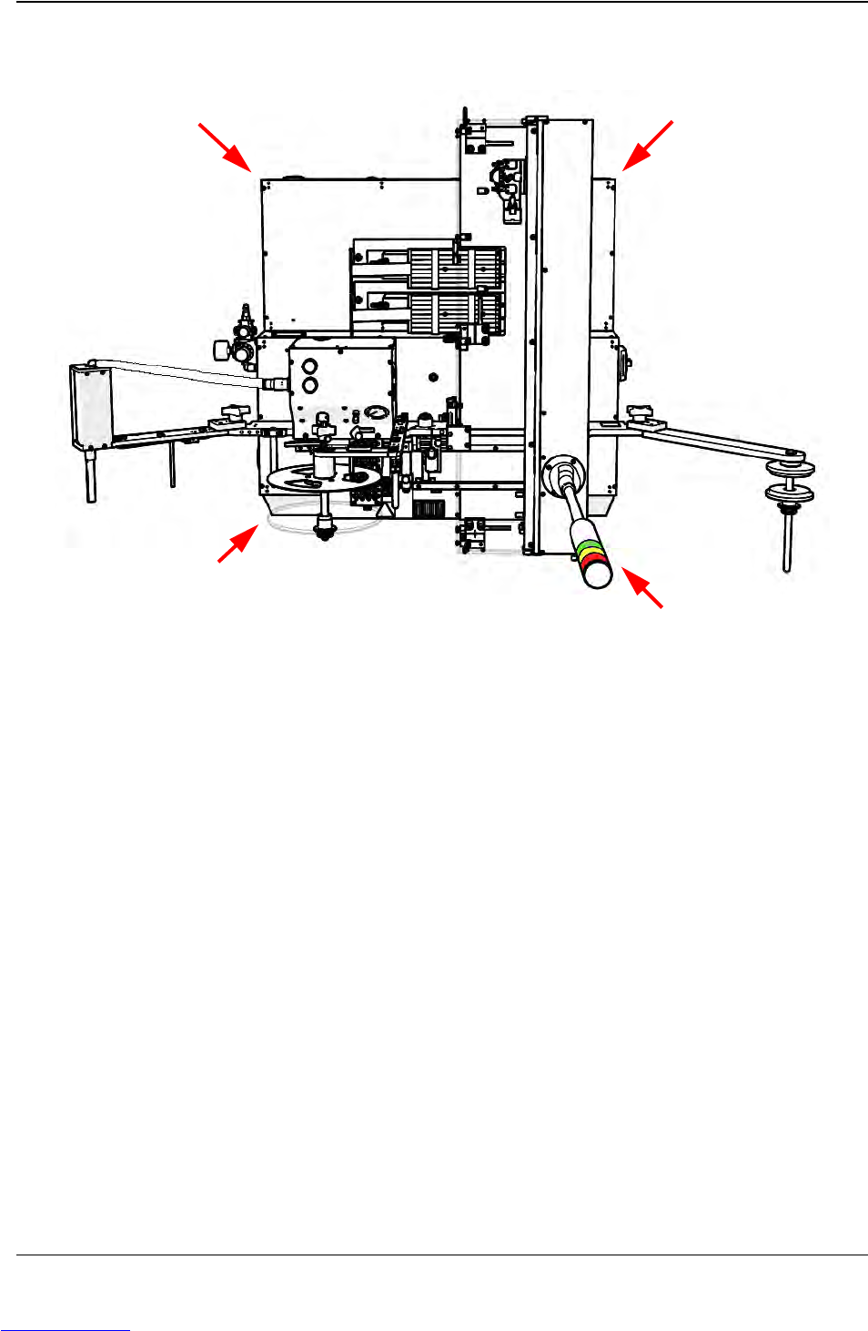
b. Moving the TM-401 Base Machine. The machine may be manually lifted from the
crate. The base machine weighs 217 lb. (98.5 Kg) so the task will require four people.
Position one person at each corner of the machine using the lift points illustrated above to
safely distribute the machine’s weight. Lift the machine from the crate and place it onto
the prepared work table/bench.
4. Position the TM-401 in the work area so there is at least 3 feet of clearance on all sides.
(See the Preparing the Work Area section earlier in this chapter for details.)
5. The TM-401 is shipped with zip ties securing the pick head, the 2D Camera and any
mobile portions of the machine. Cut and remove all zip ties.
Lift Points
Downloaded from www.Manualslib.com manuals search engine
1-8 TM-401 User’s Guide
Assembling the TM-401 D292104.4.fm
Re-assemble the TM-401
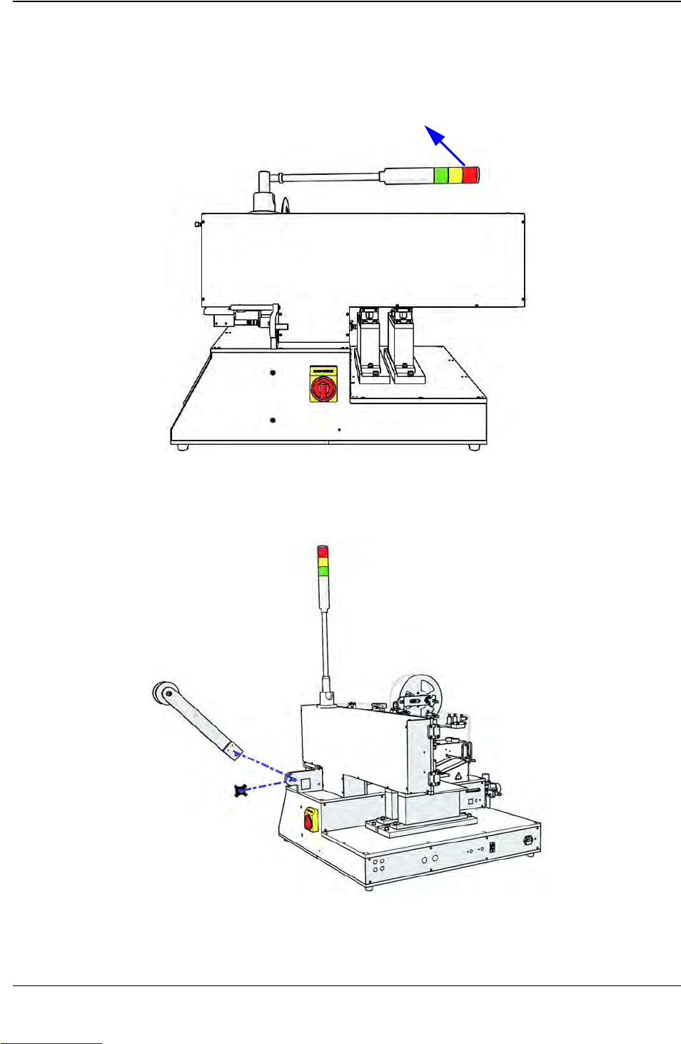
1. Position the Tower Light
Lift Tower Light, snapping it in place in an upright position perpendicular to the TM-403..
2. Connecting the Carrier Tape Arm
a. Remove the black knob from the right side of the Track Support Bracket.
Downloaded from www.Manualslib.com manuals search engine