编带机说明书-含图纸tm401.pdf - 第79页
D292104.7a.fm Load the Manual Tube Input Device (MTID) Chapter 4: Setup 4- 5 Load the Manual T ube Input De vice (MTID) The MTID must be loaded with tube s and config- ured for operation. Begin by prep aring the MTID , t…
4-4 TM-401 User’s Guide
Home Motors D292104.7a.fm
Home Motors
Note: The TM-401 needs to be homed once after each power up or Emergency
Stop activation. The HMI will prompt the operator to home the motors whenever it
is required. Once the motors have been homed, they remain homed until the
machine is powered down or the E-Stop is activated.
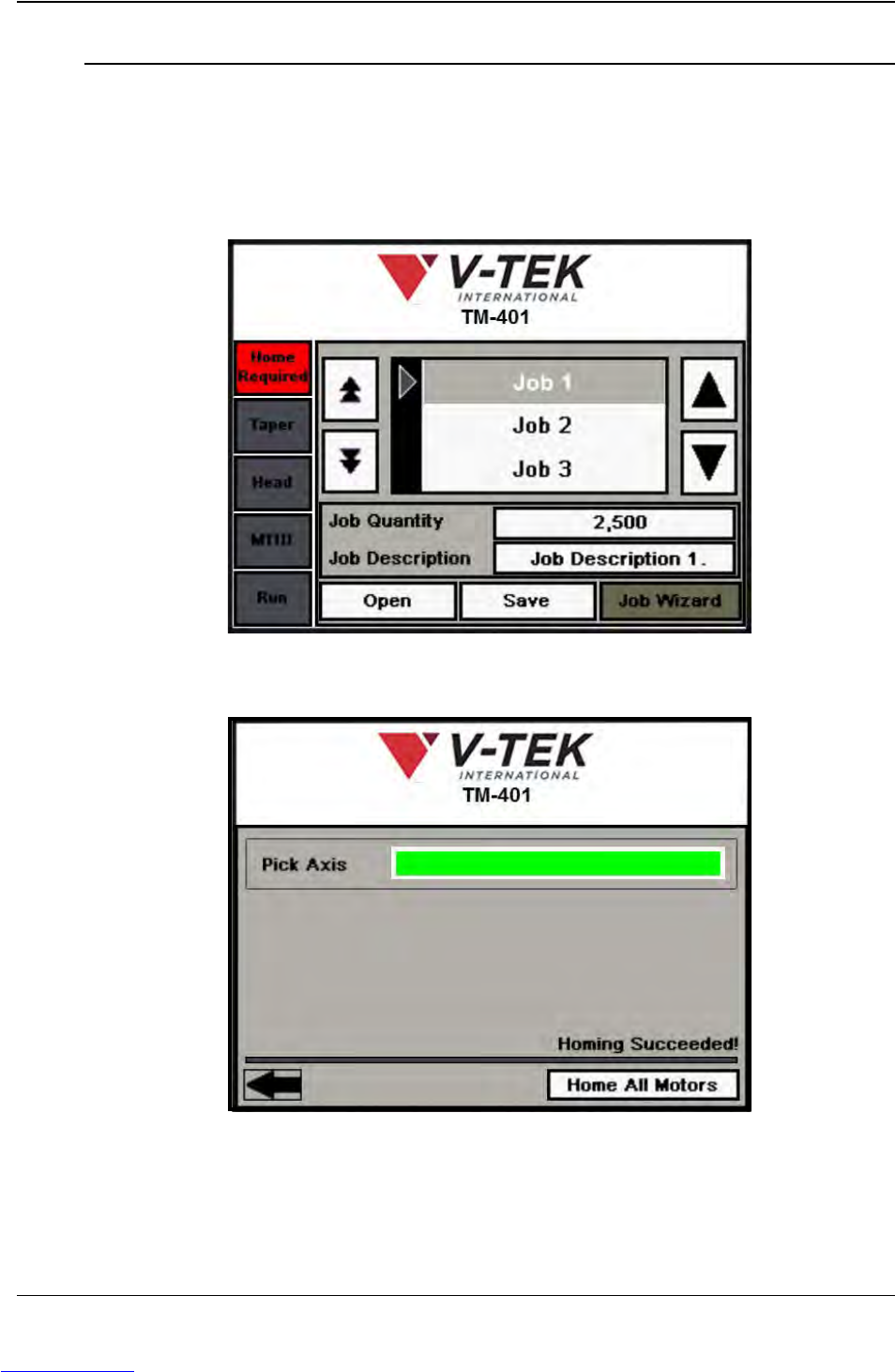
1. Press the red Home Required button at the top of the Tab Menu..
2. The TM-401 motor homing sequence begins with the pick head moving slowly to
the right towards the taper (X Axis movement).
When the head has stopped moving, homing is complete.
Step 2:
Home
Motors
Downloaded from www.Manualslib.com manuals search engine
D292104.7a.fm Load the Manual Tube Input Device (MTID)
Chapter 4: Setup 4- 5
Load the Manual Tube Input Device (MTID)
The MTID must be loaded with tubes and config-
ured for operation. Begin by preparing the MTID,
then move to the HMI to adjust settings as
needed (Step 6). Follow the directions below to
setup the Tube Feeder.
1. Ensure the correct tooling for the selected
part is installed on the feeder. If new
tooling needs to be loaded, follow the
steps below to change tooling
A. Remove all tubes from the feeder,
plugging the end of the tubes before
removal.
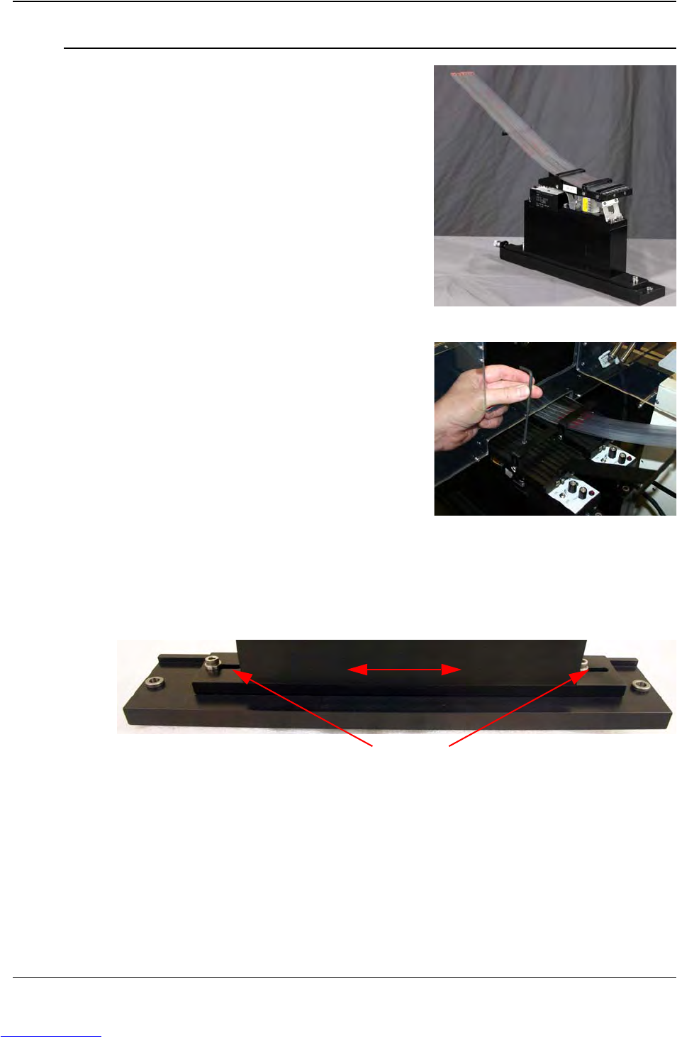
B. Using a 9/64’ Hex wrench, remove the
(2) socket head cap screws in the Tooling
Platform.
C. Remove the Tooling Platform.
D. Insert the correct Tooling Platform,
positioning it on the dowel pins to ensure
correct placement.
E. Insert the (2) socket head cap screws
and tighten in place.
2. Loosen the Clamping Bolts on the bottom of the MTID and move the Slotted Plate
so the Pick Area is centered under the Nozzle.
Note: For longer parts, the Feeder will need to be positioned closer to the Pick
Head Bridge. For shorter parts, move the Feeder closer to the Enclosure Doors.
Step 3:
Load the
MTID
Y Axis Clamping Bolts
Adjust Feeder position on Slotted Plate
Downloaded from www.Manualslib.com manuals search engine
4-6 TM-401 User’s Guide
Load the Manual Tube Input Device (MTID) D292104.7a.fm
3. Load the Manual Tube Input Device (MTID)
with tubes.
The maximum number of tubes that can be
loaded is determined by the size of the
tubes that are loaded.
The minimum number of tubes is one.
Note: The TM-401 is designed to work with
one or two MTIDs. If two MTIDs were
included with this TM-401, install them both
at this time.
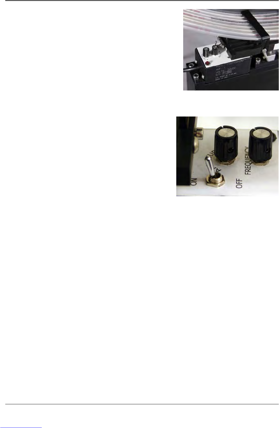
4. Turn the Vibratory ON
5. Adjust the Vibratory Frequency (speed)
and Amplitude (strength) Controls as
needed. Parts should feed fluidly but not
so rapidly that it causes parts to begin
jumping around.
Step 3:
Setup
MTID
Downloaded from www.Manualslib.com manuals search engine