编带机说明书-含图纸tm401.pdf - 第64页
3-22 TM-401 User’s Guide Head Tab D292104.6.fm Head T ab The three Head Setup T ab screens allow the user to set pick a nd place head positions, head speed, and blow of f time. There are also buttons that allow the user …
D292104.6.fm Taper Tab
Chapter 3: Human Machine Interface 3-21
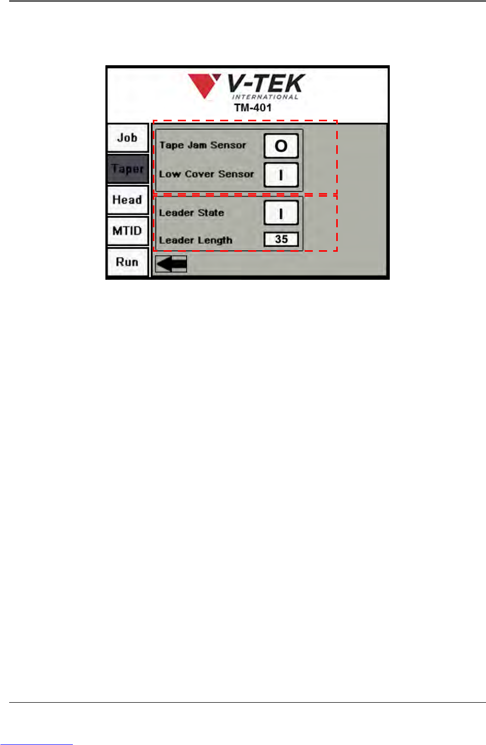
Pressing the right Arrow button in the third Taper Setup screens opens the final Taper Setup
screen. The fourth Taper Setup screen focuses on Leader and Sensor settings.
A. The Tape Jam Sensor ON ( I ) or OFF (O) button turns the Tape Jam Sensor on
and off. The Tape Jam Sensor registers a tape jam whenever something pro-
trudes above the top of the carrier tape pocket. This might be caused by a mis-
placed part, a pocket that has been loaded with two parts or by a buckle in the
tape.
When the Tape Jam Sensor is activated, the job that is being run is paused and an
error message appears on the HMI screen. The recommended setting for the
Tape Jam Sensor is ON.
The Low Cover Sensor ON ( I ) or OFF (O) button turns the Low Cover Tape Sen-
sor on and off. The Low Cover Tape Sensor detects when the cover tape reel is
running low. When the Low Cover Tape Sensor is activated, an error message
appears on the HMI screen. The recommended setting for the Low Cover Tape
Sensor is ON.
Note: The Low Cover error message is only displayed once during a job.
B. When Leader State is ON ( I ), the TM-401 will create a leader of the specified
length at the end of the job.
The Leader Length field is only active when Leader State is ON. Enter the
desired leader length in millimeters in the field.
Note: The TM-401 will use these settings for the current job. To save Taper Settings for
future jobs, go to the Job Tab, select a job name and Save. If settings are not saved, all
data is lost when the TM-401 is powered off.
Taper Screen 4
A
B
Downloaded from www.Manualslib.com manuals search engine
3-22 TM-401 User’s Guide
Head Tab D292104.6.fm
Head Tab
The three Head Setup Tab screens allow the user to set pick and place head positions, head
speed, and blow off time. There are also buttons that allow the user to manually pick, place and
rotate parts.
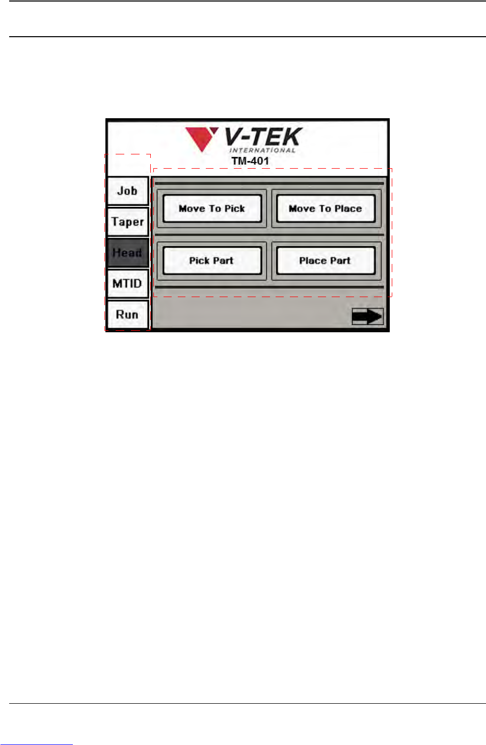
A. Press any tab in the Tab Menu to open that tab window.
B. The Move To Pick button moves the head to the preset Pick Positions.
The Move To Place button moves the pick head to the preset Place Position.
The Pick Part button moves the head from its current location and picks a part
from the programmed pick location. It then returns the nozzle to its Ready
(retracted) position.
The Place Part button moves the head from its current location and places a part
into the programmed place position.
A
B
Head Screen 1
Downloaded from www.Manualslib.com manuals search engine
D292104.6.fm Head Tab
Chapter 3: Human Machine Interface 3-23
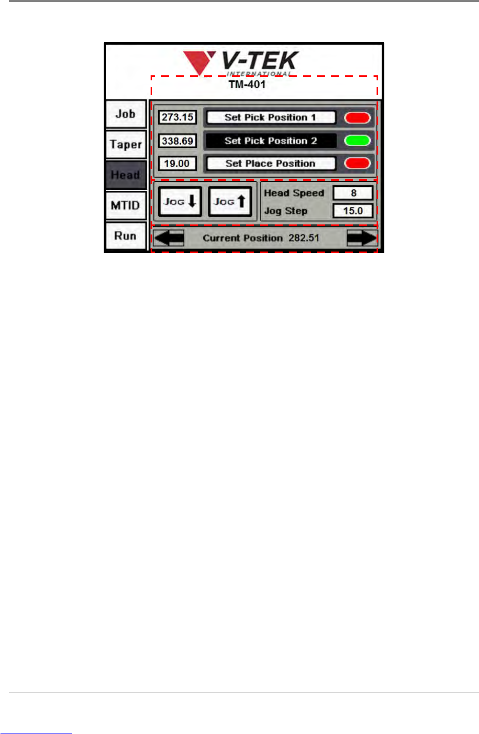
Press the right Arrow button to open the second Head Setup screen (shown below).
A. The user can either jog the head to the correct position or click inside the location
field to the left of the Set buttons and manually enter the correct position. Once
the correct position is entered, press the Set Pick/Place Position button to save
it.
•The Set Pick Position 1 button saves the current position as the pick position
for the first tube in the feeder.
•The Set Pick Position 2 button saves the current position as the pick position
for the last tube in the feeder.
•The Set Place button saves the current position as the place position.
If the position has been learned, the status color after the button will appear
green. If not learned, the status color will appear red. In the screen above, both
the Pick Position and the Place Position have not been learned.
B. The Jog buttons jog the head forward or backward along the X Axis (forward/
backward).
Head Speed is a percentage of the maximum velocity. It can be set between 1-10.
Jog Step is the distance in millimeters that the head will move when Jog is
pressed.
Note: The Jog Step field requires the value to be entered in the following format: XX.XX.
(i.e. 60.00).
C. The Current Position message show the location of the pick head in relation to the
Home position (when the head is closest to the front of the machine). For example when
Head Screen 2
A
C
B
Downloaded from www.Manualslib.com manuals search engine