编带机说明书-含图纸tm401.pdf - 第24页
1-4 TM-401 User’s Guide Preparing the Work Area D292104.4.fm When positioning the TM-401, choose an area that is not located be low overhead gantries, walk- ways or power lines to ensure objects or liqui ds cannot be dro…
D292104.4.fm Preparing the Work Area
Chapter 1: Assembly & Installation 1- 3
Table Requirements
The TM-401 should be placed on a user-supplied table or bench that is capable of supporting a
minimum of 230 lb. (104.5 Kg). An optional 80/20 frame (pictured above) is also available for
mounting the TM-401.
Choose a table that is at least 30” wide by 30” deep to provide sufficient space for the assembled
machine when it is fully loaded with a variety of tape reel sizes.
Ideally the table height should be adjustable so the machine height can be easily adjusted to suit
operators of varying heights. The objective is to position the TM-401 controls so they are easily
accessible for operation and maintenance. The suggested level is 36” (900 mm) above the floor,
but this may vary from one operator to another.
The table’s working surface should have a slope of no more than 5 degrees. Ensure that the TM-
401 feet is positioned on a table or the optional 80/20 frame so the machine is fully supported,
immobilized and level during operation.
Clearance
Allow at least three feet of clearance on all sides of the machine for easy access and operation.
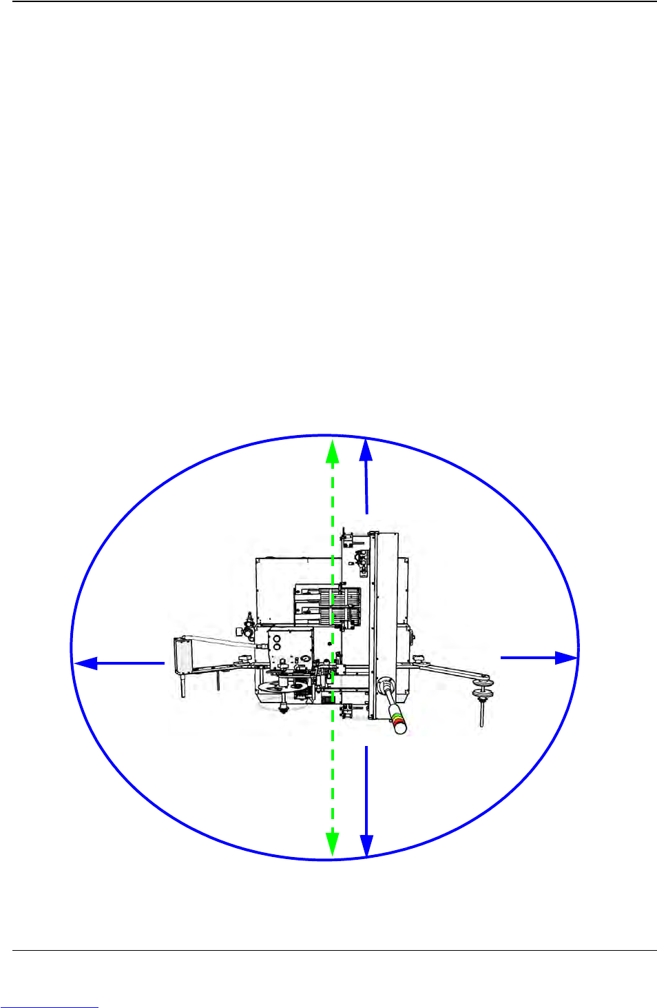
A birds-eye view of the TM-401 with minimum clearance on all sides is shown below.
Minimum clearance
3’ on all sides
Minimum Work
Space Depth
9 feet x 11 feet
Downloaded from www.Manualslib.com manuals search engine

1-4 TM-401 User’s Guide
Preparing the Work Area D292104.4.fm
When positioning the TM-401, choose an area that is not located below overhead gantries, walk-
ways or power lines to ensure objects or liquids cannot be dropped on the machine from over-
head.
Power Requirements
The TM-401 will also require access to a 85-110 PSI air pressure system and a 120/240 VAC,
50/60 Hz power supply. Locate the machine so electrical power cables can be routed away from
areas where personnel are expected to move.
Note: It is recommended that cables be routed overhead or underground. If cables must
be routed over the floor, cover them with rubber ramps.
Downloaded from www.Manualslib.com manuals search engine
D292104.4.fm Unpacking the TM-401
Chapter 1: Assembly & Installation 1- 5
Unpacking the TM-401
Prior to shipment, the TM-401 is partially disassembled, then shrink wrapped, placed in a crate,
and strapped to the crate floor. The disassembled TM-401 parts, which include the Carrier Tape
Arm, the Take-up Assembly, the Tower Light and the Spare Parts Kit, are individually bubble-
wrapped and packed around the base machine. The TM-401 crate should contain the base
machine along with the following items.
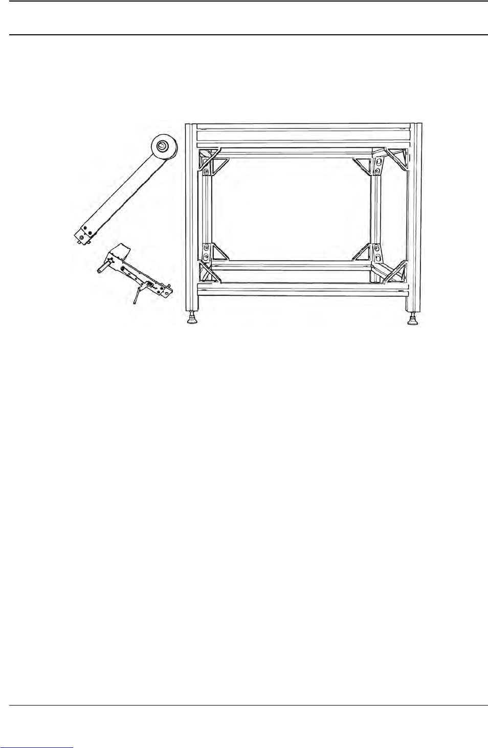
A. Carrier Tape Arm
B. 80/20 Frame (optional, shipped disassembled)
C. Take-up Arm
D. Laptop Computer (optional, not pictured)
A User’s Guide, Standard and Metric Hex Wrench Sets, and a Spare Parts Kit are also included
but not pictured above.
A
B
C
Downloaded from www.Manualslib.com manuals search engine