编带机说明书-含图纸tm401.pdf - 第43页
Chapter 3: Human Machine Interface Content s Introduction . . . . . . . . . . . . . . . . . . . . . . . . . . . . . . . . . . . . . . . . . . . . . . . . 3-2 T ouc h Screen . . . . . . . . . . . . . . . . . . . . . . . .…
2-12 TM-401 User’s Guide
2D Vision System D292104.5a.fm
2D Vision System
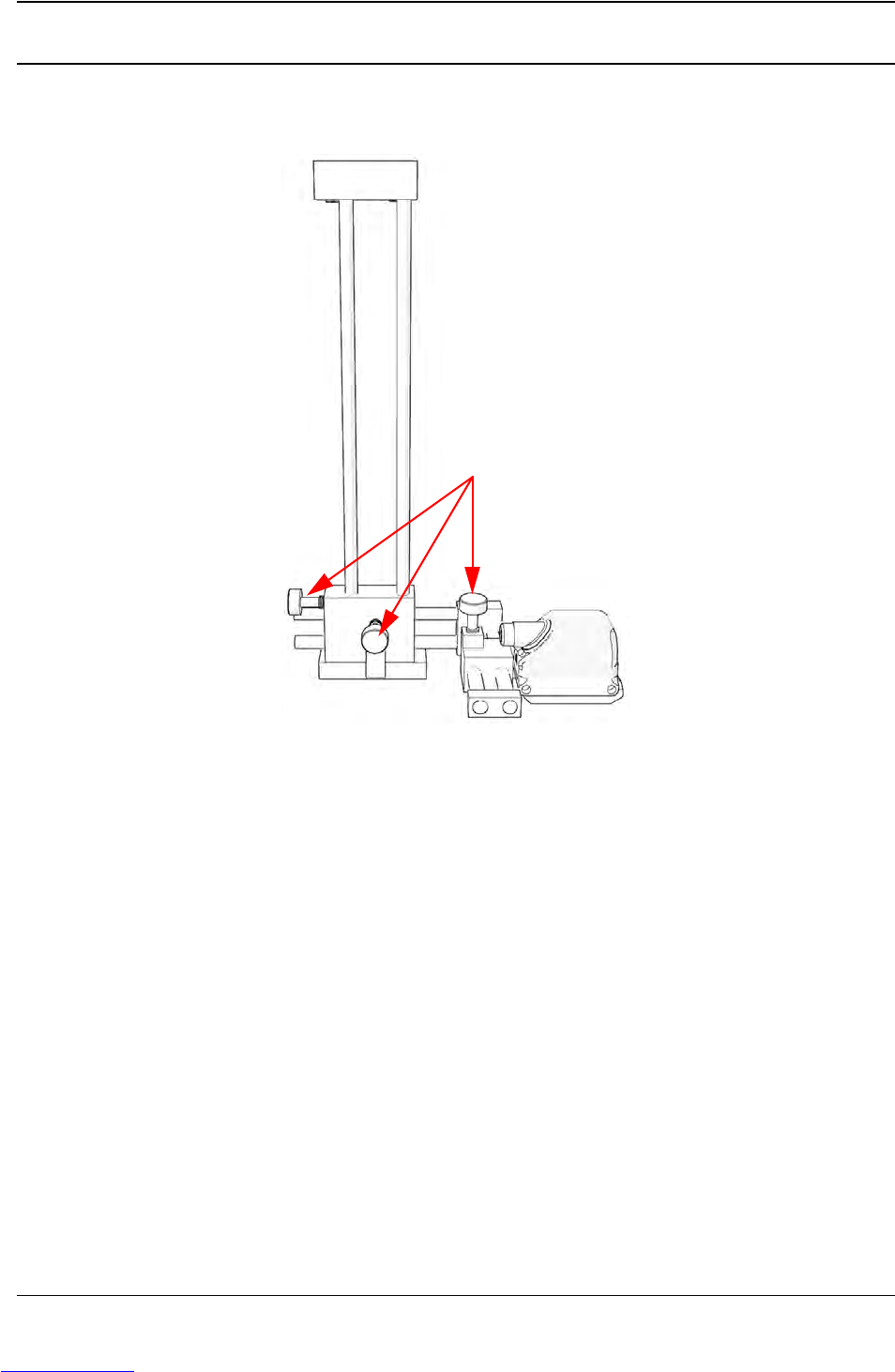
The Keyence IV Vision system consists of the following components shown below.
A. Adjustable Mounting Bracket F. Status LED
B. Position Adjustment Knobs G. Ethernet Traffic Indicator
C. Power & I/O Connector H. Keyence IV-G Camera
D. Ethernet Connector I. Lens Cover/Focus Ring
E. M12 Ethernet Cable (not shown)
Note: For advanced Vision configuration, a computer is required. This can be provided by
the user or purchased as an option from V-TEK, Inc. System requirements for the vision
computer follow:
• Operating system: Microsoft® Windows 7
TM
(32 or 64 bit)
• 128 MB RAM
• 1024 x 768 (96 DPI) or 1280 x 1024 (120 DPI display
• Ethernet port
A
B
C
Downloaded from www.Manualslib.com manuals search engine

Chapter 3: Human Machine Interface
Contents
Introduction . . . . . . . . . . . . . . . . . . . . . . . . . . . . . . . . . . . . . . . . . . . . . . . .3-2
Touch Screen. . . . . . . . . . . . . . . . . . . . . . . . . . . . . . . . . . . . . . . . . . . . . . . . . . 3-2
HMI Tabs . . . . . . . . . . . . . . . . . . . . . . . . . . . . . . . . . . . . . . . . . . . . . . . . . . . . . 3-2
Job Tab . . . . . . . . . . . . . . . . . . . . . . . . . . . . . . . . . . . . . . . . . . . . . . . . . . . .3-4
Job Wizard. . . . . . . . . . . . . . . . . . . . . . . . . . . . . . . . . . . . . . . . . . . . . . . . . . . . 3-7
Taper Tab . . . . . . . . . . . . . . . . . . . . . . . . . . . . . . . . . . . . . . . . . . . . . . . . . .3-18
Head Tab . . . . . . . . . . . . . . . . . . . . . . . . . . . . . . . . . . . . . . . . . . . . . . . . . . .3-22
MTID Tab . . . . . . . . . . . . . . . . . . . . . . . . . . . . . . . . . . . . . . . . . . . . . . . . . . .3-26
Run Tab. . . . . . . . . . . . . . . . . . . . . . . . . . . . . . . . . . . . . . . . . . . . . . . . . . . .3-29
Downloaded from www.Manualslib.com manuals search engine
3-2 TM-401 User’s Guide
Introduction D292104.6.fm
Introduction
This chapter gives an overview of the TM-401 Human Machine Interface (HMI), defining the but-
tons, screens and setting options that allow the operator to customize the TM-401’s performance
to their taping needs.
Note: Proceed to Chapter 4: Setup for instructions on how to configure the HMI and to
Chapter 5: Operation for instructions on how to run a job
Touch Screen
The user interacts with the TM-401 through a touch screen HMI which is located on the front of
the machine below the Taper. Touching the HMI screen has the same effect as a left click with the
mouse. Although only lightly touching the buttons or data fields is necessary for activation, the
action is referred to as “pressing” in this manual.
Note: Use care when operating the touch screen and do not use any objects other than a
finger to touch the screen. A stylus can also be used to click the various buttons.
HMI Tabs
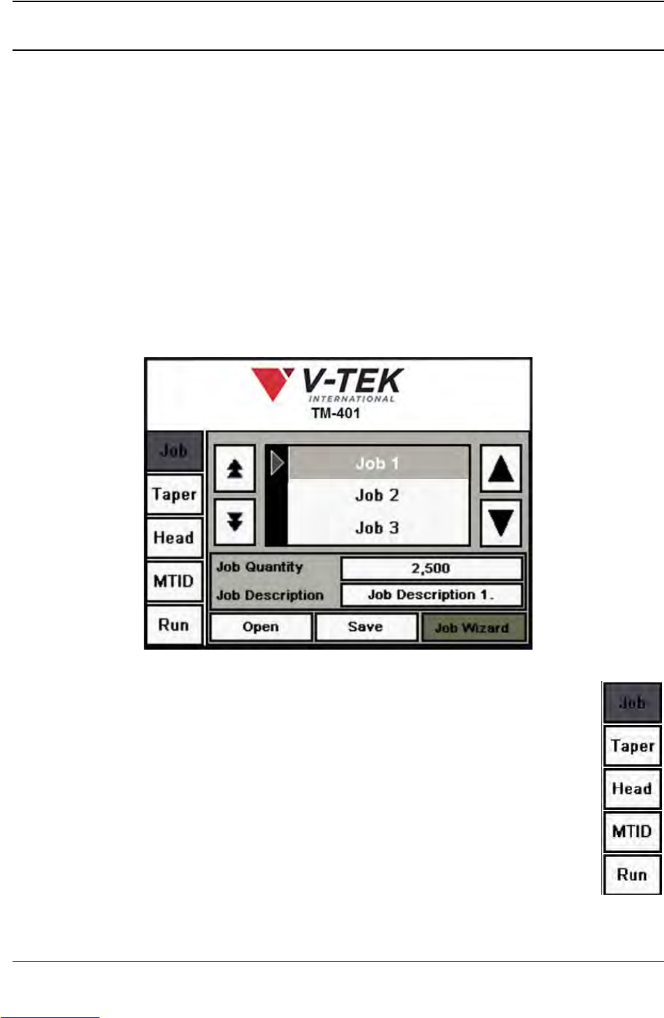
When the TM-401 is powered on, the user interface opens to the Job Tab. The Job
Tab is pictured above as it appears when the motors have been homed.
There are five tabs on the TM-401 HMI: Job, Taper, Head, MTID (Manual Tube Input
Device) and Run. These tabs allow the user to configure pick head, taper, tube
feeder and job settings and to run jobs.
The Tab Menu (pictured on the right) is located on the left side of all screens. To nav-
igate between tabs, press the desired tab name on the Tab Menu and the selected
tab will open.
Downloaded from www.Manualslib.com manuals search engine