4OM-1625-004_w.pdf - 第331页
4OM-1603 1012-005 5-B

4OM-1603
1012-005 5-A
Chapter 5
Troubleshooting on Component Picks and Placement
This chapter describes the scope of troubleshooting on component picks
and placement.
1.ClassicationofFailureSymptomsandHelpfulHintson
Countermeasures against Failure
2. Troubleshooting on Pickup Errors
3. Troubleshooting on Component Placement Errors

4OM-1603
1012-005 5-B
4OM-1603
5-1
1.ClassicationofFailureSymptomsandHelpfulHintsonCountermeasuresagainstFailure:Chap.5
1012-005
1. ClassicationofFailureSymptomsandHelpfulHints
on Countermeasures against Failure
1.1 ClassicationofFailureSymptoms
The machine processes can be classied into Processes A, B, C, D, and E as
shown below.
Reference
Refer to "4. Surface Mounting Mechanism" in "Chapter 1 (Vol. 1: Guide)" for
the outline of actions.
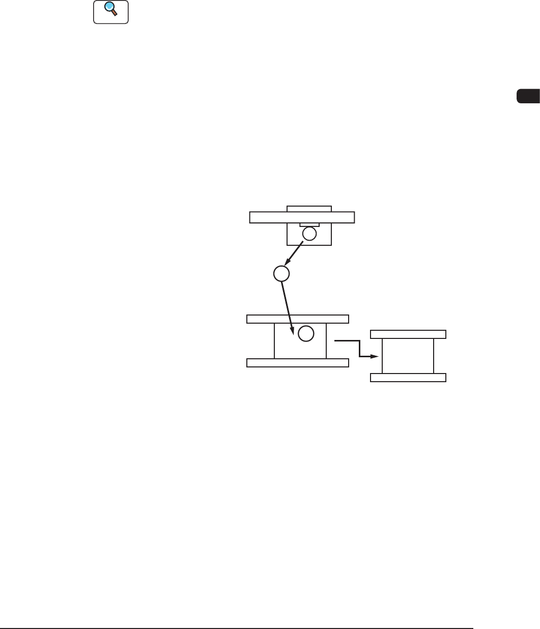
Process A : The placement head moves to the feeder base and picks up a
component.
Process B : The head moves to the area where the component recognition
camera is installed and a component recognition process is
taken there.
Process C : The placement angle is corrected while the head is moving to
the PCB positioning section.
Process D : The component is placed on the PCB.
Process E : The component-placed PCB is discharged.
1
2
3
Feeder Base Section
Component Recognition Camera
PCB Positioning Section
Process A
Process B
Process C
Process D
Process E
F4E1
Based on these processes, failures can be divided roughly into the following two
types.
Failure before Component Placement : This type of failure occurs mainly in
Processes A, B, and C.
Failure after Component Placement : This type of failure occurs mainly at
Processes D and E.