EN 3.pdf - 第281页
Model DECAN Series Company SAMSUNG TECHWIN Module 3.15 PC RACK V ersion 01 Tit le PC RACK DUMMY SLOT SEP ARA TION Page 3-15-12 Note [PC RACK DUMMY SLOT SEP ARA TION] 1. T urn off the PC and turn of f the Main Switch in t…
Model
DECAN Series
Company
SAMSUNG TECHWIN
Module
3.15 PC RACK
Version
01
Title
COOLING FAN CHANGE
Page
3-15-11
Note
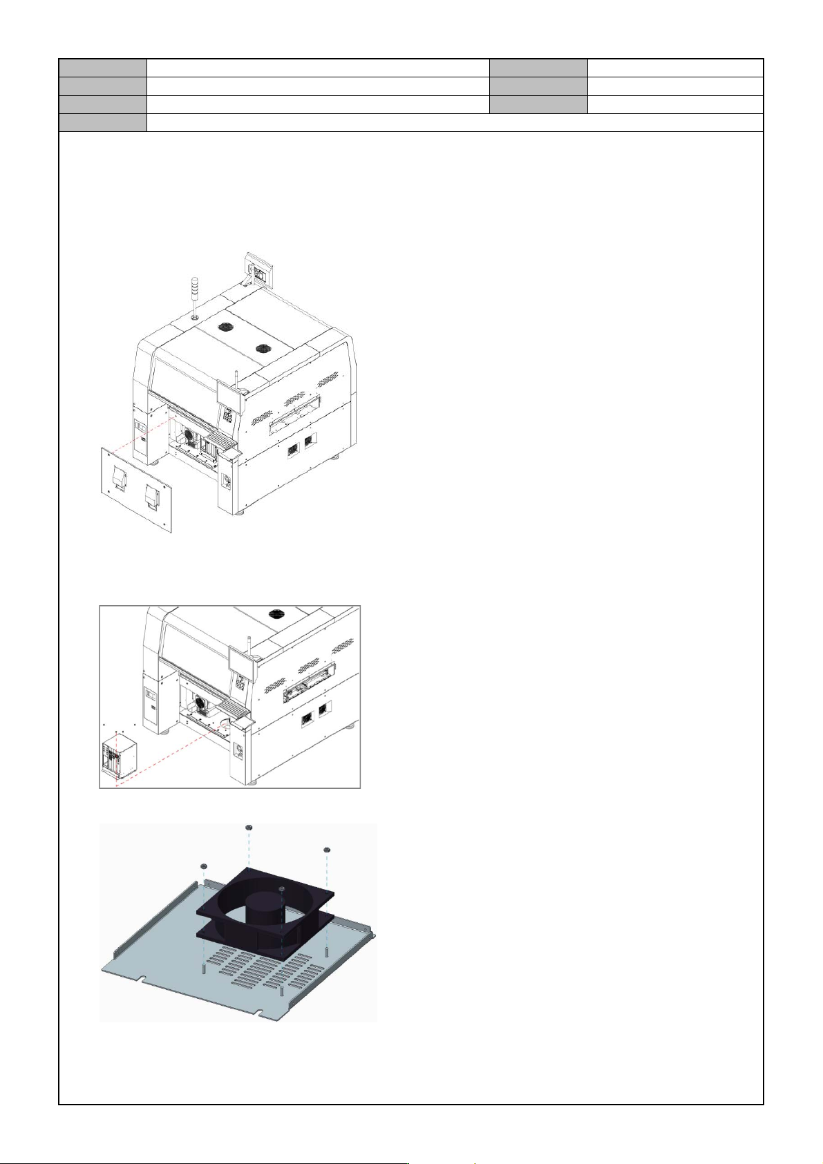
[COOLING FAN CHANGE]
1. Turn off the PC and turn off the Main Switch in the front of the equipment.
2. Separate the front cover from the equipment.
3. Separate the cable from the PC Rack.
4. Release the fixing bolts for the PC Rack and separate the PC Rack.
5. Separate the fan by releasing the fixing bolts for the fan in the bottom panel of the PC Rack.
6. Pay attention to the direction so that the new fan does not blow the wind out of the panel.
Model
DECAN Series
Company
SAMSUNG TECHWIN
Module
3.15 PC RACK
Version
01
Title
PC RACK DUMMY SLOT SEPARATION
Page
3-15-12
Note
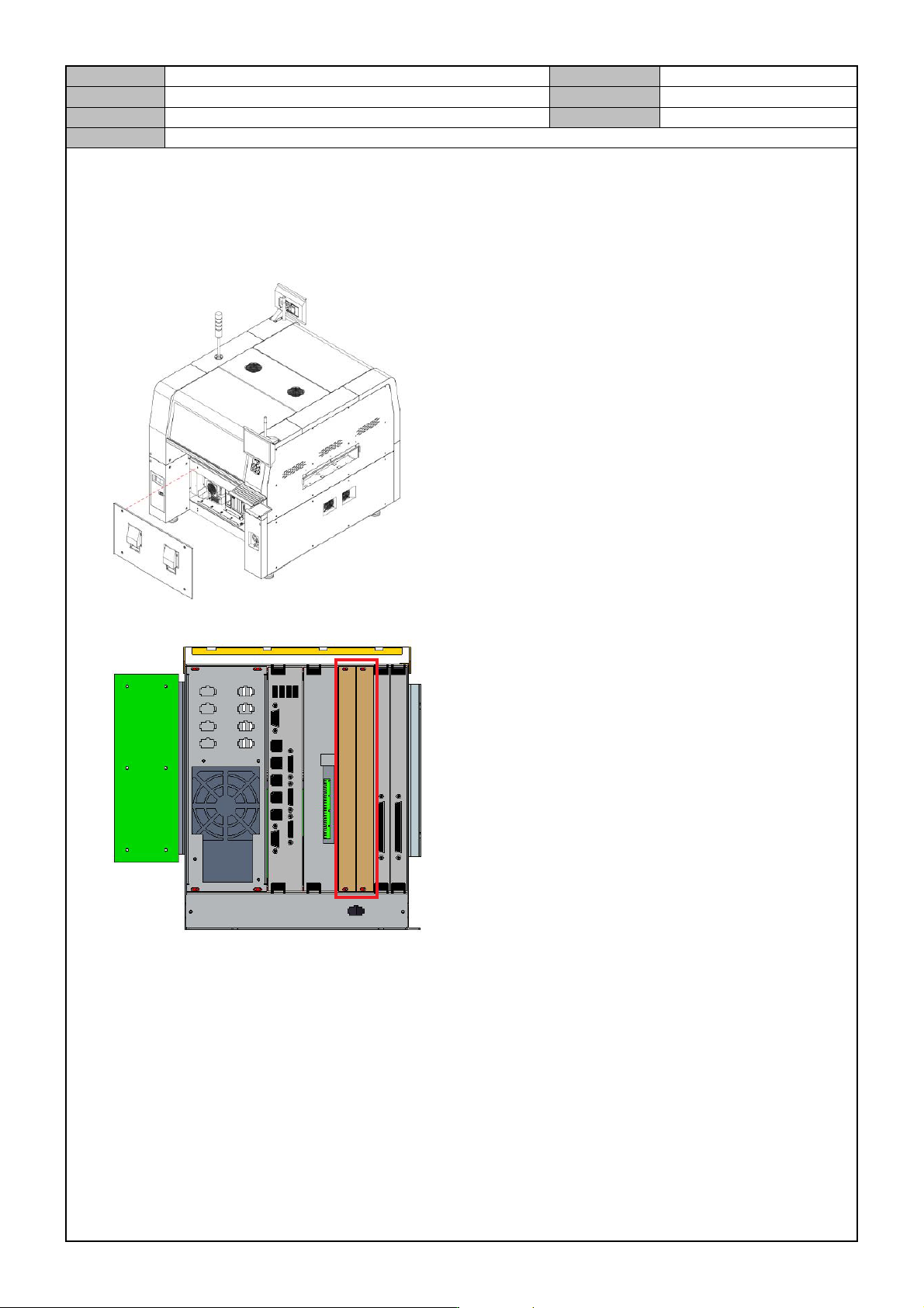
[PC RACK DUMMY SLOT SEPARATION]
1. Turn off the PC and turn off the Main Switch in the front of the equipment.
2. Separate the front cover from the equipment.
3. Separate the dummy slot cover to discharge heats from the inside of the PC rack.

Model
DECAN Series
Company
SAMSUNG TECHWIN
Module
3.16 X-FRAME
Total Pages
15
Table of Contents
[FX Z PHASE CHECK & COUPLING ASSEMBLY] ............................................. 2
[FLAT CABLE ASSEMBLY] ................................................................................. 3
[GREASE INJECTION] ........................................................................................ 5
[X AXIS NOISE DECISION CRITERIA] ............................................................... 6
[XY-DUCT X AXIS CABLE WIRING] ................................................................... 7
[XY DUCT INSPECTION] .................................................................................. 10
[XY EXTERIOR CHECK] ................................................................................... 11
[MOTOR DRIVER ASSEMBLY]......................................................................... 12
[LIMIT SENSOR REPLACEMENT] .................................................................... 14
[X AXIS LM GUIDE BOLT REASSEMBLY] ....................................................... 15