EN 3.pdf - 第338页
Model DECAN Series Company SAMSUNG TECHWIN Module 3.19 ELECTRIC DEVICE V ersion 01 Tit le VOL T AGE CHECK TEST Page 3-19-12 Note 7. T urn the MCCB on. 8. T urn CP#1,2,3 off. 9. CP#1,2,3 input power measurem ent No. Inspe…
Model
DECAN Series
Company
SAMSUNG TECHWIN
Module
3.19 ELECTRIC DEVICE
Version
01
Title
VOLTAGE CHECK TEST
Page
3-19-11
Note
[VOLTAGE CHECK TEST]
AC/DC power activated with Ready OFF.
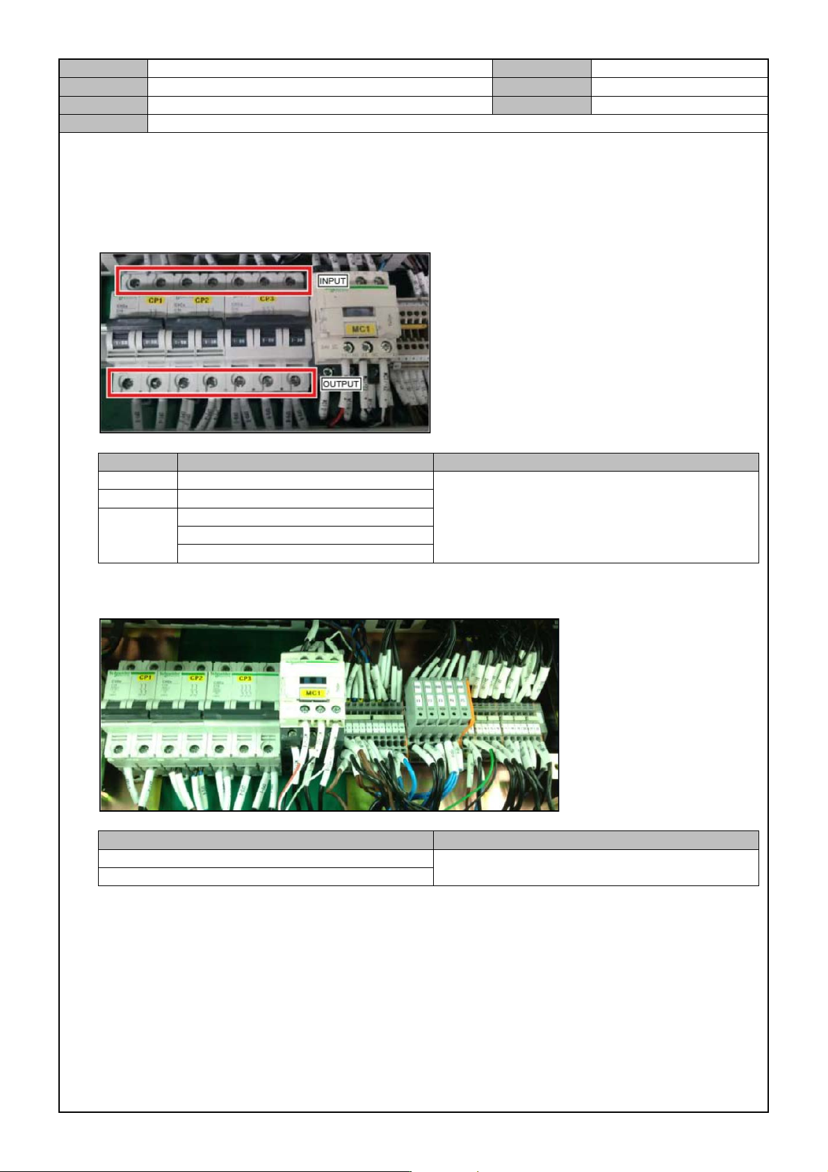
1. Measure the output power of CP#1,2,3.
No. Inspection units Inspection criteria
CP#1 CP#1 output power : CP1-2 , CP1-4
AC 220V±10
CP#2 CP#2 output power : CP2-2 , CP2-4
CP#3
CP#3 output power : CP3-2 , CP3-4
CP#3 output power : CP3-2, CP3-6
CP#3 output power : CP3-4 , CP3-6
*Condition : CP#1 ON, CP#2 OFF, CP#3 OFF
2. TB#1 AC power measurement
Inspection units Inspection criteria
TB1 AC power measurement : 1L1 , 1L2
AC 220V±10
TB1 AC power measurement : 22R , 22T
*Condition : CP#1 ON, CP#2 ON, CP#3 ON
3. Separate the CN1/2 connectors from the Safety Control Board.
4. Separate the FY1,2 RY1,FX,FS RX RS control power connectors.
5. Turn CP#1,2,3 off.
6. Connect the Main Power Cable to the three phase power terminal.
Model
DECAN Series
Company
SAMSUNG TECHWIN
Module
3.19 ELECTRIC DEVICE
Version
01
Title
VOLTAGE CHECK TEST
Page
3-19-12
Note
7. Turn the MCCB on.
8. Turn CP#1,2,3 off.
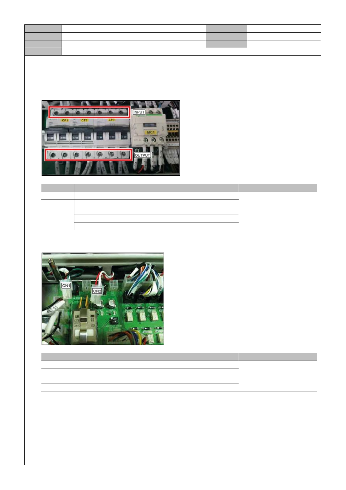
9. CP#1,2,3 input power measurement
No. Inspection units Inspection criteria
CP#1 CP#1 input power : CP1-1 , CP1-3
AC 220V±10
CP#2 CP#2 input power : CP2-1 , CP2-3
CP#3
CP#3 input power : CP3-1 , CP3-3
CP#3 input power : CP3-1 , CP3-5
CP#3 input power : CP3-3 , CP3-5
*Condition : CP#1 OFF, CP#2 OFF, CP#3 OFF
10. Safety Control Board CN1,CN2 DC power measurement
Inspection units Inspection criteria
SAFETY CONTROL B/D CN1 : CN1-1 , CN1-3
DC 24V±0.72
SAFETY CONTROL B/D CN1 : CN1-2 , CN1-4
SAFETY CONTROL B/D CN2 : CN2-1 , CN2-3
SAFETY CONTROL B/D CN2 : CN2-2 , CN2-4
*Condition : CP#1 ON, CP#2 ON, CP#3 ON
Model
DECAN Series
Company
SAMSUNG TECHWIN
Module
3.19 ELECTRIC DEVICE
Version
01
Title
VOLTAGE CHECK TEST
Page
3-19-13
Note
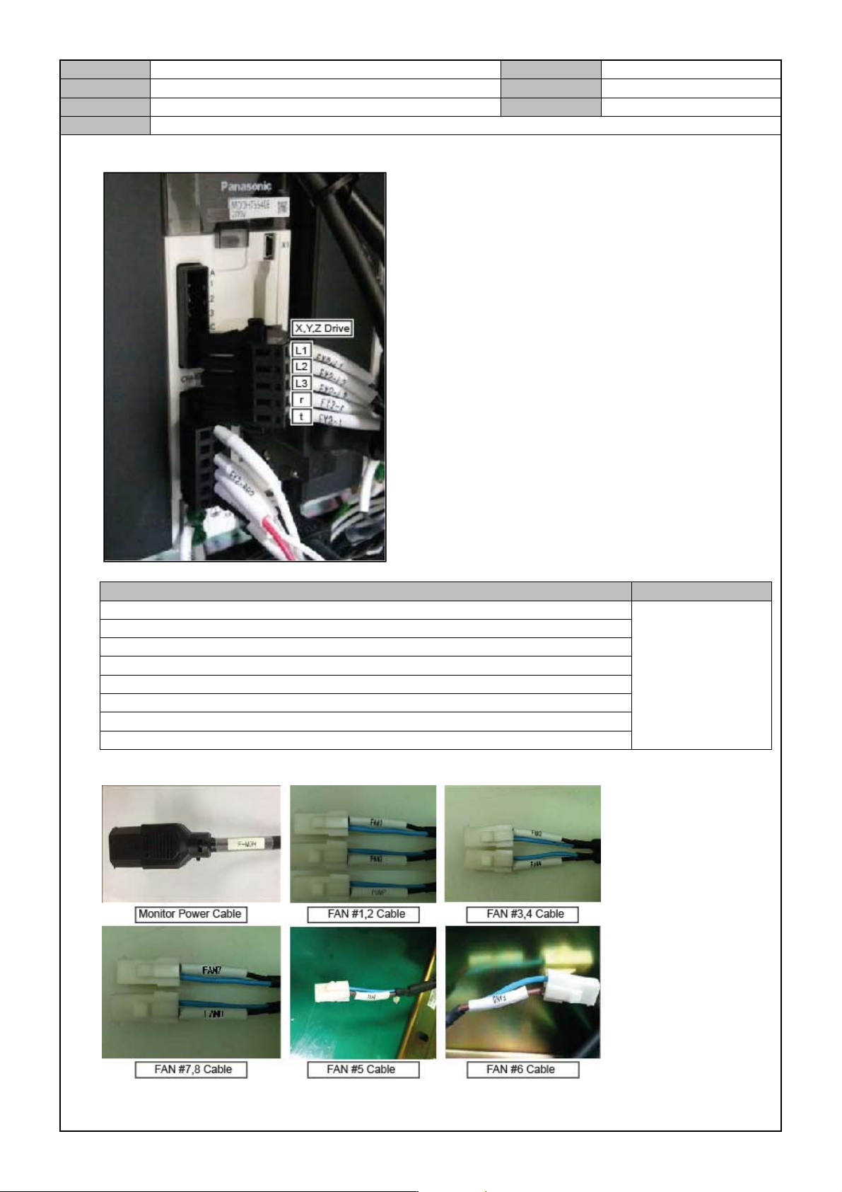
11. Motor Driver Control Power(FY1,FY2,RY1, RY2FX,RX,FSW,RSW) measurement.
Inspection units Inspection criteria
MOTOR DRIVER CONTROL POWER FS axis X1 : 1(FS-t) , 2(FS-r)
AC 220V±10
MOTOR DRIVER CONTROL POWER FX axis X1 : 1(FX-t) , 2(FX-r)
MOTOR DRIVER CONTROL POWER RS axis X1 : 1(RS-t) , 2(RS-r)
MOTOR DRIVER CONTROL POWER RX axis X1 : 1(RX-t) , 2(RX-r)
MOTOR DRIVER CONTROL POWER FY1 axis X1 : 1(FY1-t) , 2(FY1-r)
MOTOR DRIVER CONTROL POWER FY2 axis X1 : 1(FY2X-t) , 2(FY2-r)
MOTOR DRIVER CONTROL POWER RY1 axis X1 : 1(RY1-t) , 2(RY1-r)
MOTOR DRIVER CONTROL POWER RY2 axis X1 : 1(RY2-t) , 2(RY2-r)
12. FAN #1~8, Front/Rear Monitor, PC Rack power are measured in the following order.