1OM-1626-001_w.pdf - 第106页
1OM-1610 2-7 2. Operation Screen : Chap.2 2.3 Control Menu When the [Control] button is pressed on the common menu bar, the "Control menu" window appears. In the "Cont rol menu" window, gr oups of the…
1OM-1610
2-6
2. Operation Screen : Chap.2
0911-001
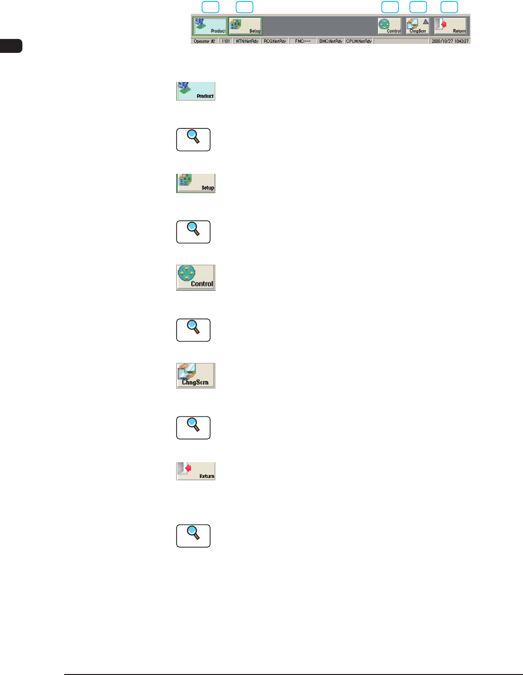
2.2 Common Menu Bar
When the window is logged in using the [Product] or [Set-up] button, the
following common menu bar is displayed.
[1] [2] [3] [4] [5]
Common Menu Bar F1B6
[1] [Product] Button
When this button is pressed, the "Product" window is displayed.
Reference
Refer to "Menus for Automatic Operation" in "Chapter1 (Volume 2)" for
the detailed information on the "Product" window.
[2] [Setup] Button
When this button is pressed, the "Set-up" window is displayed.
Reference
Refer to "Menus for Setup Operation" in "Chapter2 (Volume 2)" for the
detailed information on the "Set-up" window.
[3] [Control] Button
When pressed, this button opens the "Cont. Prgm" window.
Reference
Refer to "2.3 Control Menu" for the detailed information on the "Control"
window.
[4] [Chng Scrn] Button
When this button is pressed, the "Chng Scrn" window is displayed.
Reference
Refer to "2.4 Chng Scrn" for the detailed information on the "Chng Scrn"
window.
[5] [Return] Button
When this button is pressed, the operation window is closed and the "TOP"
window is returned.
Reference
Refer to "Exiting from the System Program" for the detailed information
on the "LOGOUT " window.
1OM-1610
2-7
2. Operation Screen : Chap.2
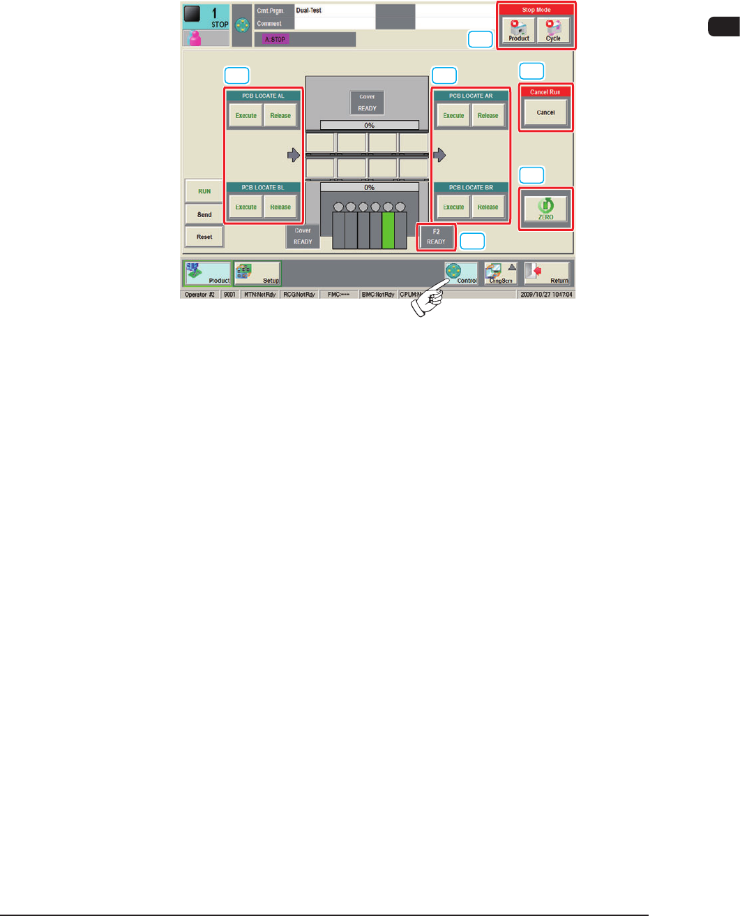
2.3 Control Menu
When the [Control] button is pressed on the common menu bar, the "Control
menu" window appears.
In the "Control menu" window, groups of the basic operation buttons are arranged.
[1] [1]
[3]
[4]
[5]
[2]
F1B6-1
[1] PCB LOCATE
AL, AR, BL, BR
[Execute] Button
When the [Execute] button is pressed and within 10 seconds, the [START]
button on the operation panel is pressed, the backup base and clamp are lifted
and the PCB on the PCB positioning unit is positioned.
[Release] Button
When the [Release] button is pressed and within 10 seconds, the [START]
button on the operation panel is pressed, the backup base and clamp are
lowered and the positioned PCB is released.
0911-001

1OM-1610
2-8
2. Operation Screen : Chap.2
[2] [F2 READY] Button
When the [F2 READY] button is pressed, the feeder ready switches on the
main machine are turned ON/OFF, and feeder clamp holding bar is locked/
unlocked.
Note
The moving up/down operation of the feeder base is unavailable. If
needed, perform it using the feeder ready switches on the main machine.
Reference
Refer to "2.3 Feeder Ready Switches and Cover Lock Switches" in Chapter
1, for the feeder ready switches on the main machine.
[3] Stop Mode
[Product] Button
When this button is pressed, after the production of the PCB which is in
the course of the production, is completed, the PCB is discharged and the
automatic operation is stopped.
[Cycle] Button
When this button is pressed, after the component placement operation on the
PCB which is in the course of the production, is completed, the automatic
operation is stopped.
[4]
Cancel Run
[Cancel] Button
When the machine status is turned to "Pause", the [Cancel] button is
displayed. When the [Cancel] button is pressed, the "Pause" status is
cancelled and the machine is in the "Stop" mode.
[5] [ZERO] Button
After the [ZERO] button is pressed and within 10 seconds, the [START]
button on the operation panel is pressed, all the axes are zeroed.
0911-001