1OM-1626-001_w.pdf - 第173页
1OM-1610 4-16 3. Program Change Operation : Chap.4 3.5 ConrmationofPCBT ransferandPositioning The following describes how to check the status of the PCB transfer and positioning in the "PCB XFER" window …

1OM-1610
4-15
3. Program Change Operation : Chap.4
(5) Slide the nozzle stocker shutter and set all vacuum nozzles to be used in the
nozzle stocker.
Notice
(a) Attach the vacuum nozzles correctly in the nozzle stockers.
Do not operate the machine with a vacuum nozzle being left on the
nozzle stocker shutter. Otherwise, the machine will break down.
(b) When a middle-size odd-shaped nozzle must be set in a nozzle
stocker, the mark on the nozzle must face the right side (viewed
from the feeder side).
If the nozzle is set in a wrong direction, an "ERROR" window will
openduringthenozzleidentication,causingthe
machinetostop
running.
(6) Attach the nozzle stocker to the machine.
(7) Press the [Change] button in the "NOZ.CHG." window.
In 10 seconds, press the [START] button on the operation panel to attach the
vacuum nozzle to the placement head.
Note
When the machine is provided with an extended nozzle stocker (option)
and vacuum nozzles (to be used after a program change operation) are
prepared in the extended stocker, the nozzles are stored and attached in
succession.
(8) Select the [Conrm] button in the "NOZ.CHG." window and press the
[START] button on the operation panel to check if the correct nozzles are
attached or not.
0911-001
1OM-1610
4-16
3. Program Change Operation : Chap.4
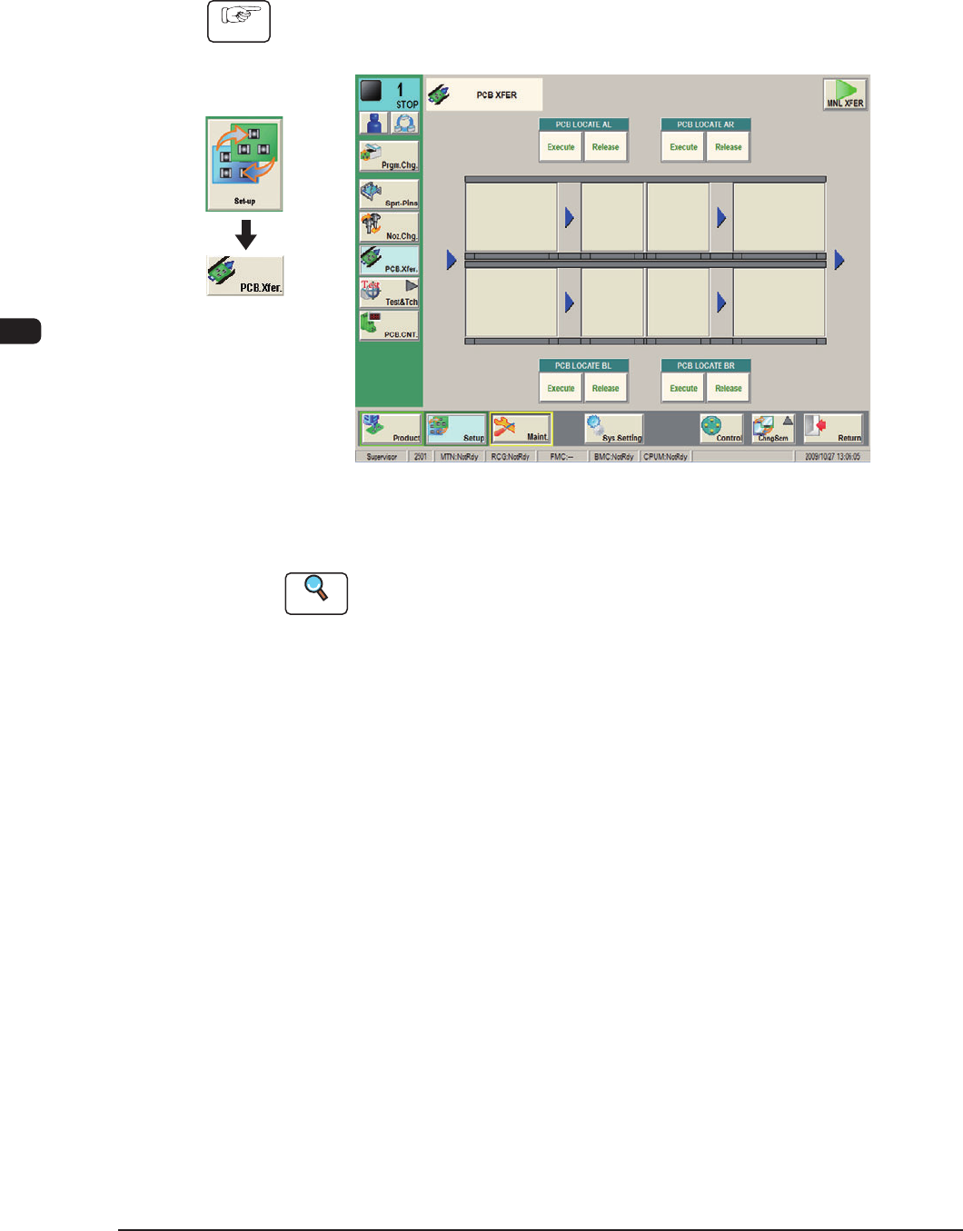
3.5 ConrmationofPCBTransferandPositioning
The following describes how to check the status of the PCB transfer and
positioning in the "PCB XFER" window (a menu of "AUTO OPN").
Procedure
(1) Display the "PCB XFER" window using the following icon procedure.
F1D17
(2) Input the PCB from the input machine.
Reference
When the PCB is to be input manually, refer to "3.1.1 PCB Manual Input
Procedure", in Chapter 3.
(3) Select a desired block button (expressed graphically) for "PCB LOCATE L".
In 10 seconds, press the [START] button on the operation panel to transfer
the PCB.
(4) Conrm that the PCB can be transferred normally and move smoothly
without falling down during the transfer.
(5) Press the [Execute] button (entitled "PCB LOCATE L").
In 10 seconds, press the [START] button on the operation panel.
The backup base moves up.
(6) Press the cover lock switch to turn off the lamp.
The transparent cover (door type) is unlocked.
Graphic
Development
0911-001

1OM-1610
4-17
3. Program Change Operation : Chap.4
(7) Open the transparent cover (door type).
CAUTION
The load power to the motors, etc., is turned OFF
but the setup operation must be performed carefully
when you put your hand inside the machine. Avoid
handandngerinjuries.
(8) Slightly push the PCB by nger to conrm that there is no problem in the
location of the support pins.
(9) Close the transparent cover (door type).
(10) Press the cover lock switch to turn on the lamp.
0911-001