1OM-1626-001_w.pdf - 第93页
1OM-1610 1-36 4. Surface Mounting Mechanism : Chap.1 091 1-001 4.1.5 Component Picks The vacuum nozzles on the placement head are used to pick up the components. 4.1.6 Component Recognition Each head is also provided wit…
1OM-1610
4. Surface Mounting Mechanism : Chap.1
1-350911-001
4.1 PCB Input and Component Placement
In Stage 1 (the stage on the input section side), the rst half of the component
placement processing is made.
4.1.1 PCB Input
The PCB sent from the input machine is transferred and reaches the PCB
positioning section.
4.1.2 PCB Positioning
The PCB is detected by the transferred PCB detection sensor in the PCB
positioning section and positioned there.
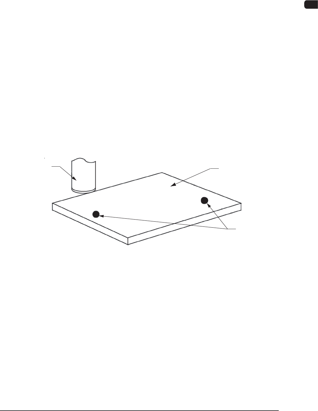
4.1.3 Detection and Correction of Positional Deviations with PEC
Recognition Camera
The PEC recognition camera detects the ducial marks on the PCB and the
positional deviations are calculated to correct the position of the components to be
placed.
Fiducial Marks
PCB
PCB Recognition
Camera
PEC Recognition
F1A30
4.1.4 Component Supply
The tape feeder on the feeder base is shifted to the position where the components
must be supplied.
The placement head is also shifted in the X and Y directions by the X/Y beam and
picks up a component. After that, it places the picked component on the PCB.
1OM-1610
1-36
4. Surface Mounting Mechanism : Chap.1
0911-001
4.1.5 Component Picks
The vacuum nozzles on the placement head are used to pick up the components.
4.1.6 Component Recognition
Each head is also provided with a line sensor. The line sensor is used to detect a
component to be picked up and a vertical component. It is also used to measure
the component thickness.
The image of the component picked up by the vacuum nozzle is captured by the
component recognition camera for the inspection.
The back and front lighting recognition systems are adopted for component
recognition with the component recognition camera. Either one of the systems is
selected automatically according to the lighting mode specied in the component
library data.
Reference
Refer to "3.9 Component Recognition Section [Short Appendix]: Principle of
Component Recognition" for details.
Component Recognition Process
The following three operations are performed in the component recognition
system.
•
Component Detection
All components are regarded as object components for the detection.
•
Component Inspection
Various inspections are made according to the component library data.
•
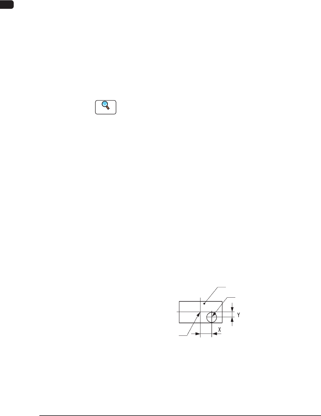
Measurement of Component’s Positional and Angular Deviations
Measured are the positional deviations (X, Y) and the angular deviation (
q
)
between the centers of the component recognition camera and the component.
Center of Component
Component
Center of Component
Vacuum Nozzle
State of Component Picked Up by Vacuum Nozzle F1A31
1OM-1610
4. Surface Mounting Mechanism : Chap.1
1-370911-001
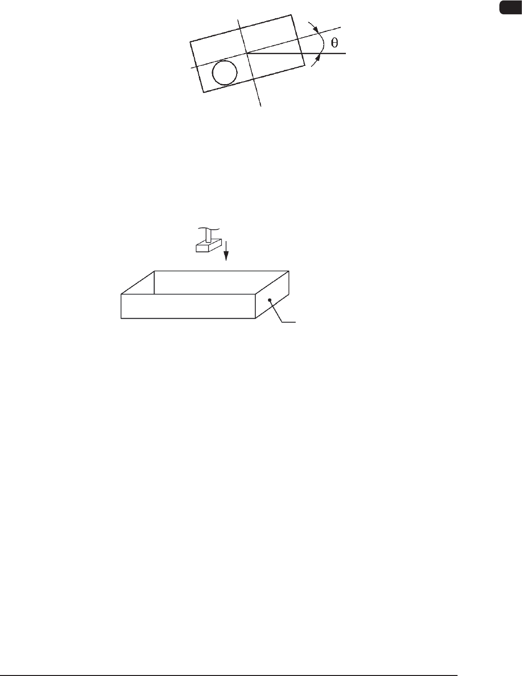
Recognition Correction (Angular Correction)
The picked component is adjusted to the angle (placement direction) of placement
specied in the pattern program by rotating the head. At this time, the angular
deviation (
q
) detected through component recognition is also corrected.
F1A32
Component Discharge (Component Storage Box)
When a recognition error occurs during the component recognition, the placement
head moves to the component storage box and discharges the error-caused
component.
Component Storage Box
Component Discharge F1A33
4.1.7 Component Placement
The placement head moves to the point (the coordinates for the placement)
specied in the pattern program for the PCB in the standby mode in the PCB
positioning section. At this time, the positional deviations (X, Y) measured
through the component recognition are adjusted correctly for proper component
picks.
The lowest limit of the vacuum nozzle is controlled according to the component
library data.
The solenoid valve closes and the component picked up by the vacuum nozzle is
placed on the PCB.
The front and rear beams take component placement and pickup actions repeatedly
in turns, realizing efcient and continuous component mounting.