1OM-1626-001_w.pdf - 第91页
1OM-1610 1-34 4. Surface Mounting Mechanism : Chap.1 091 1-001 4. Surface Mounting Mechanism Described roughly below is how the components are placed on the PCB. PCB Transfer Chapter 1 4.1.8 in Input Machine Buffer Secti…
1OM-1610
3. Mechanism for Surface Mounting : Chap.1
1-330911-001
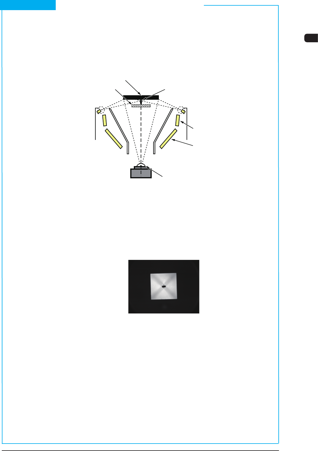
(3) Back Lighting Recognition System
The gure below shows the sectional view of the recognition section in the
back lighting recognition system and the ow of lights for the recognition.
When a component like the shadowed one in the gure is used, the outline of
the component is recognized through the back lighting.
Vacuum nozzle Components
Back Lighting
Front Lighting 3
(BGA Lighting)
Front Lighting 1
Front Lighting 2 (Coaxial Lighting)
CCD Camera
Scope
Diffusion Plate
F1A27
The lights emitted from the lamps for back lighting meet the diffusion plate
and reect to the component.
At this time, the lights that do not meet the component go into the CCD camera
through the monocular.
That is, the CCD camera captures the outline of the component.
Example : Captured Image for Recognition
F1A28
Short Appendix : Principle of Component Recognition (Continued)
1OM-1610
1-34
4. Surface Mounting Mechanism : Chap.1
0911-001
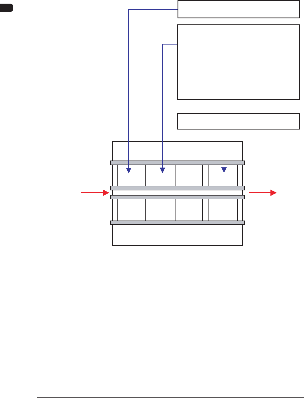
4. Surface Mounting Mechanism
Described roughly below is how the components are placed on the PCB.
PCB Transfer Chapter 1
4.1.8 in
Input
Machine
Buffer
Section
Buffer
Section
Locating "L"
Section
Locating "R"
Section
Output
Machine
PCB Input Chapter 1
PCB Output Chapter 1
4.1.1 in
PCB Positioning Chapter 1
PEC Recognition Chapter 1
Component Supply Chapter 1
Component Picks Chapter 1
Component Recognition Chapter 1
Component Placement Chapter 1
4.1.2 in
4.1.3 in
4.1.4 in
4.1.5 in
4.1.6 in
4.1.7 in
4.2.2 in
Lane A
Lane B
Flow of Surface Mounting
F1A29
1OM-1610
4. Surface Mounting Mechanism : Chap.1
1-350911-001
4.1 PCB Input and Component Placement
In Stage 1 (the stage on the input section side), the rst half of the component
placement processing is made.
4.1.1 PCB Input
The PCB sent from the input machine is transferred and reaches the PCB
positioning section.
4.1.2 PCB Positioning
The PCB is detected by the transferred PCB detection sensor in the PCB
positioning section and positioned there.
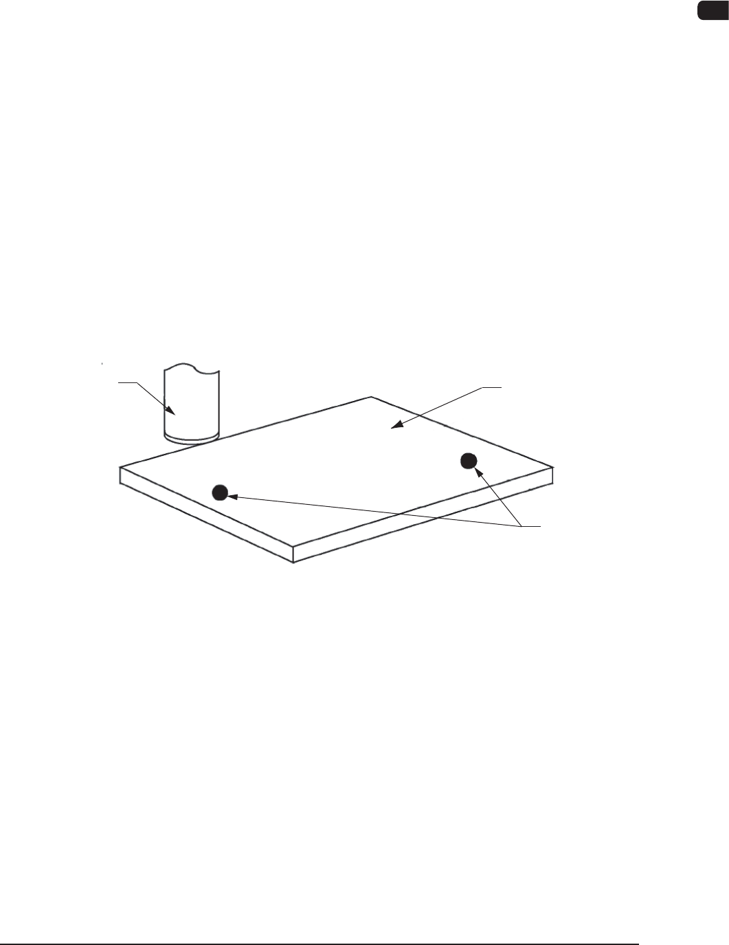
4.1.3 Detection and Correction of Positional Deviations with PEC
Recognition Camera
The PEC recognition camera detects the ducial marks on the PCB and the
positional deviations are calculated to correct the position of the components to be
placed.
Fiducial Marks
PCB
PCB Recognition
Camera
PEC Recognition
F1A30
4.1.4 Component Supply
The tape feeder on the feeder base is shifted to the position where the components
must be supplied.
The placement head is also shifted in the X and Y directions by the X/Y beam and
picks up a component. After that, it places the picked component on the PCB.