1OM-1626-001_w.pdf - 第61页
1OM-1610 1-4 2. Name and Function of Each Section : Chap.1 091 1-001 2. Name and Function of Each Section 2.1 Appearance of Machine Transparent Cover (2.4) Light Tower (2.6) Transparent Cover (2.4) Cover Lock Switch (Sta…

1OM-1610
1. What is the direct drive modular mounter? : Chap.1
1-30911-001
Recognition Unit
•
Non-Stop Fly Batch Recognition
Components can be recognized collectively without stopping the heads
that are moving at high speed. This function is called "Non-Stop Fly Batch
Recognition".
Images without any distortion can be captured though the telecentric lens,
realizing the multiple recognition. This highly accurate multiple recognition
function is used to recognize up to 15 components collectively at high speed.
Cart Installation
•
Intelligent Motor-Driven Feeders
The adoption of motors for tape feeding realized highly accurate component
supply at high speed without any hindrance even for minute fragile (weak to
shocks) components.
The machine is provided with bank feeder change carts that can be loaded
with various types of components (more than the conventional types),
reducing the time for feeder setup operations.
The tape splicing function also enabled the continuous production (non-stop
operation of the machine).
PCB Transfer Section
•
Dual
Transfer
The dual transfer function that uses two PCB feeding lanes, transfers two
PCBs from the input machine alternatively in these two lanes to enhance the
productivity.
•
PCB Height Measurement Feedback Function (Optional)
Before the machine places components on a PCB, the thickness of the PCB
upper surface is measured using a laser and is fed back to the height for
component placement.
It is possible to signicantly suppress stress imposed on components during
placement due to upward warpage of PCBs and reduce solder bridges for
high quality component placement.
1OM-1610
1-4
2. Name and Function of Each Section : Chap.1
0911-001
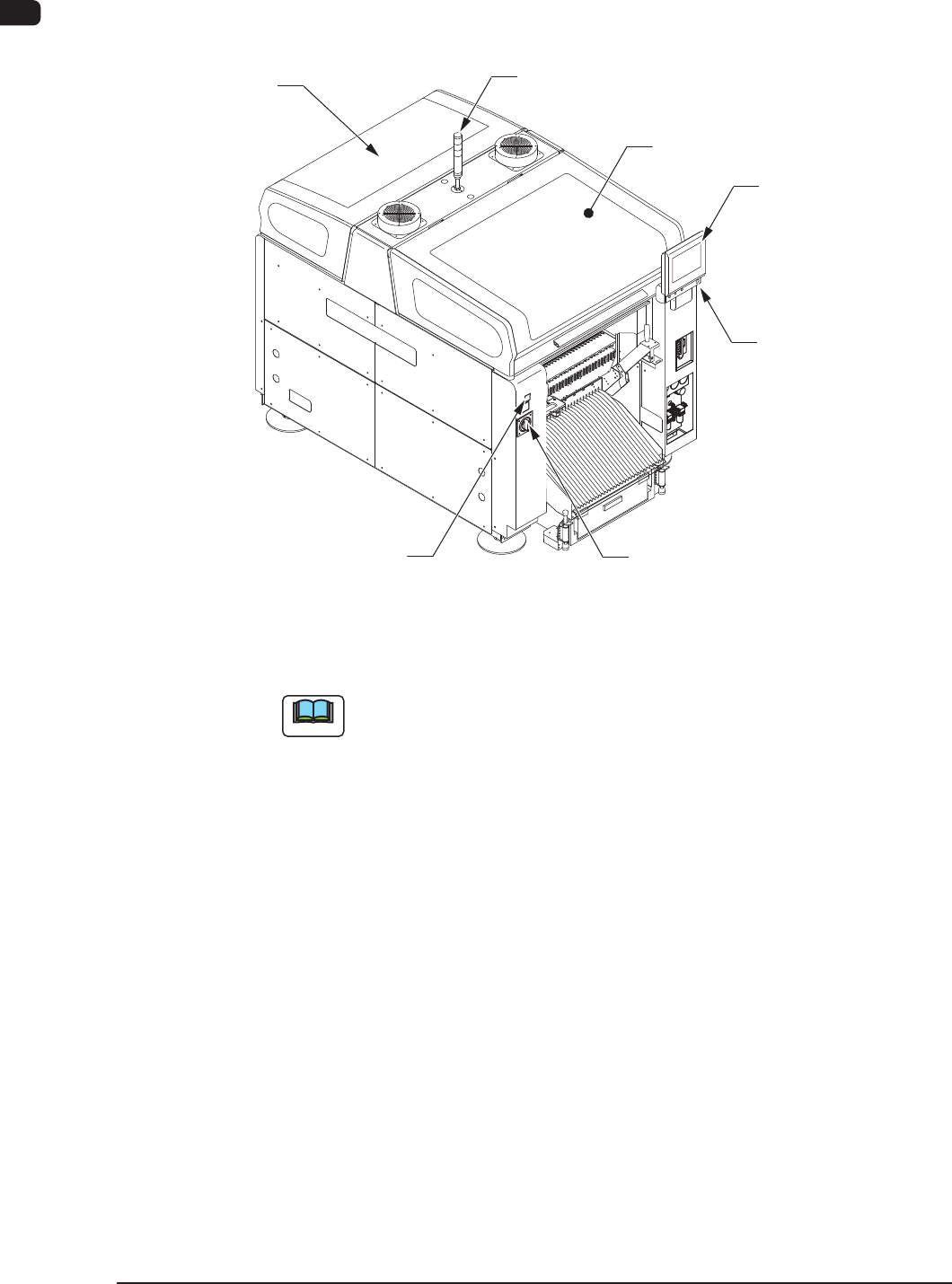
2. Name and Function of Each Section
2.1 Appearance of Machine
Transparent
Cover (2.4)
Light Tower
(2.6)
Transparent Cover
(2.4)
Cover Lock Switch
(Stage Ready Switch)
Power Breaker
(2.5)
Front Side of Machine
Front Operation Panel
(2.7)
[EMERGENCY STOP]
Switch (2.2)
F1A2
Note
The gures in brackets show the item No.
1OM-1610
2. Name and Function of Each Section : Chap.1
1-50911-001
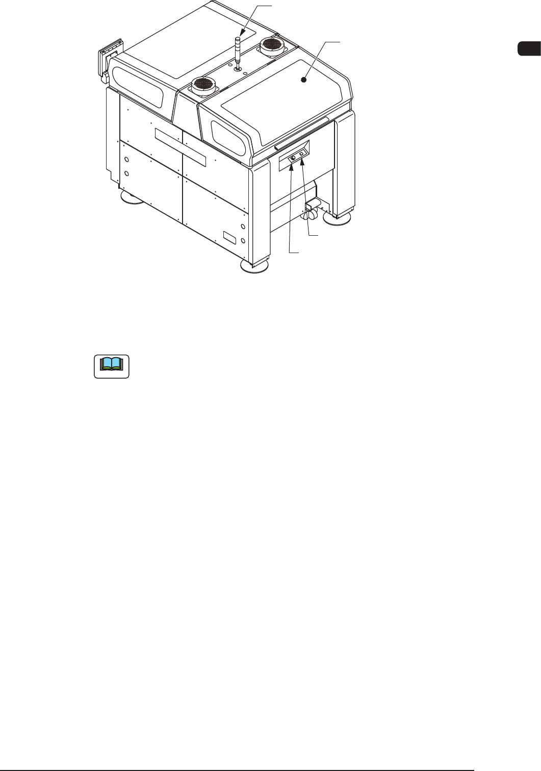
Light Tower
(2.6)
Transparent Cover
(2.4)
Cover Lock Switch
Rear Side of Machine
[EMERGENCY STOP] Switch
F1A3
Note
The gures in brackets show the item No.