1OM-1626-001_w.pdf - 第87页
1OM-1610 1-30 3. Mechanism for Surface Mounting : Chap.1 091 1-001 3.9 Component Recognition Section Each beam has a component recognition camera and a light source for illumination within its coverage area. The camera a…

1OM-1610
3. Mechanism for Surface Mounting : Chap.1
1-290911-001
(3) Release the connector set lever and pull out the connector connecting to the
bank feeder change cart, from the connector on the machine, and attach it to
the magic tape section on the side of the cart.
Notice
During the machine operation, do not disconnect the connector. For
the feeder base connector, connect or disconnect it when the feeder
base is lowered to the end and it has stopped.
(4) Release the two stopper brakes of the bank feeder change cart and draw out
the cart from the machine.
(5) Insert the bank feeder change cart (provided with the tape feeders set ready
for use) into the machine and lock the two stopper brakes
Notice
(a) When the bank feeder change cart must be pushed into the
machine, push it straight such that the guide on the machine
side can be located inside the cart arm.
(b) When the cart is not positioned correctly, the connection
operation cannot be performed.
Besuretopushthecartrmly
untilittouchesthestopper.
(6) Connect the connector of the cart to the connector on the machine side and
set the connector xing lever in place.
Notice
When the bank feeder change cart must be pushed into the
machine, push it straight such that the guide on the machine side
can be located inside the cart arm.
(7) Press the Feeder Ready switches of the machine.
The feeder base starts moving up and the LED of the Feeder Ready switches
starts ickering, indicating that the feeder base is being activated.
(8) Press the Feeder Ready switches of the machine.
The LED of the switch illuminates and the feeder clamp holding bar is
locked electromagnetically.
1OM-1610
1-30
3. Mechanism for Surface Mounting : Chap.1
0911-001
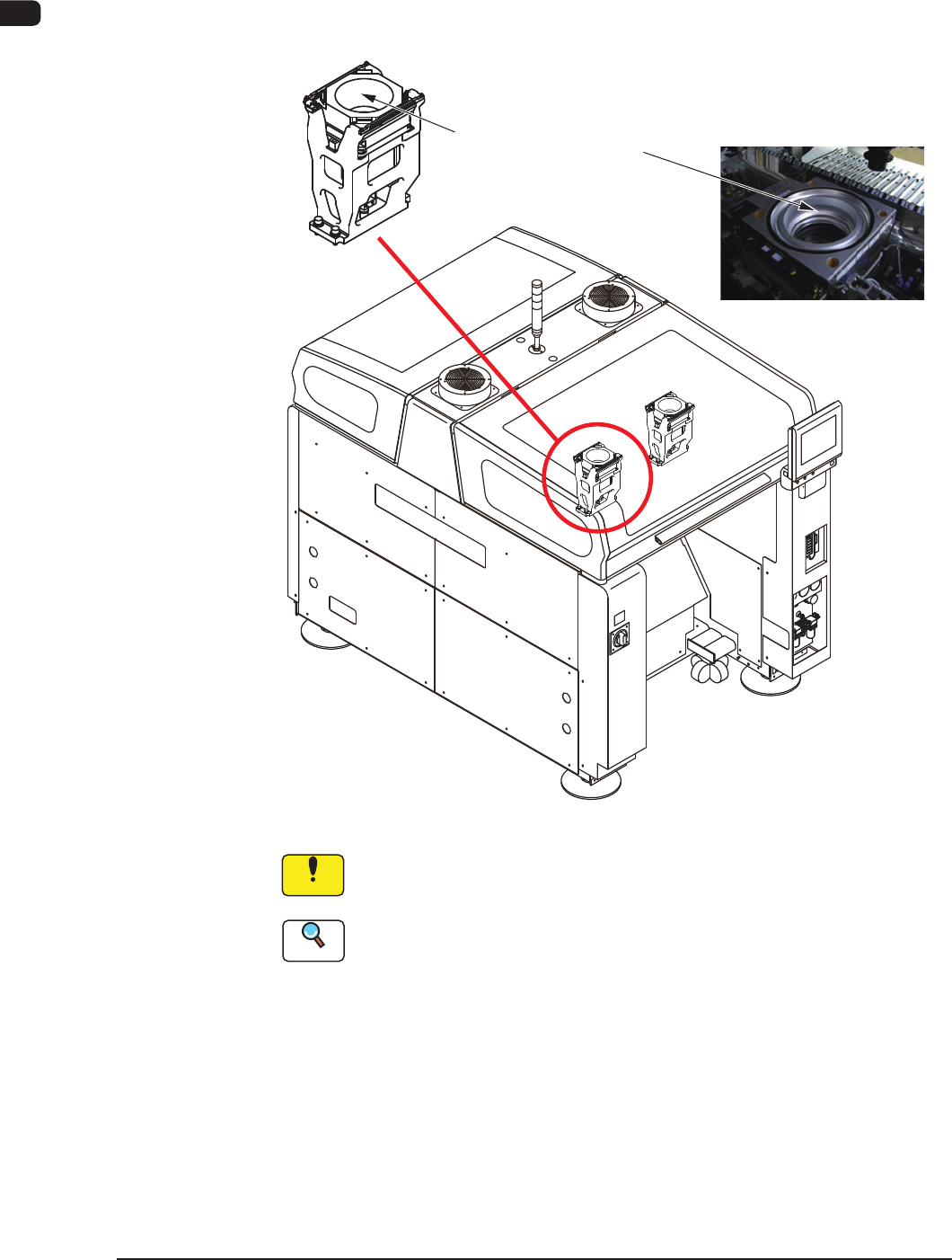
3.9 Component Recognition Section
Each beam has a component recognition camera and a light source for
illumination within its coverage area. The camera and the light source are used to
inspect (recognize) the component picked up by a vacuum nozzle.
Hood
(for BGA components)
F1A23
Notice
Do not stain the component recognition camera protective glass. Doing
so might lower the recognition accuracy.
Reference
When the protective glass becomes dirty, refer to "3.3.3 Recognition Camera
Unit" in Chapter 1, Volume 4.
The machine is provided with front and back lighting systems. In the front
lighting system, the bottom surface of a component is illuminated directly from
under the component and the reected image is captured (both ring and coaxial
lamps are used together). In the back lighting system (ring lamps), the diffusion
plate is illuminated from under the plate and the penetrated image of a component
is captured. Either one of the systems can be selected according to the components
being used.
1OM-1610
3. Mechanism for Surface Mounting : Chap.1
1-310911-001
The back and front lighting recognition systems are prepared for component
recognition. Either one of them is selected automatically according to the
lighting mode specied in the component library data.
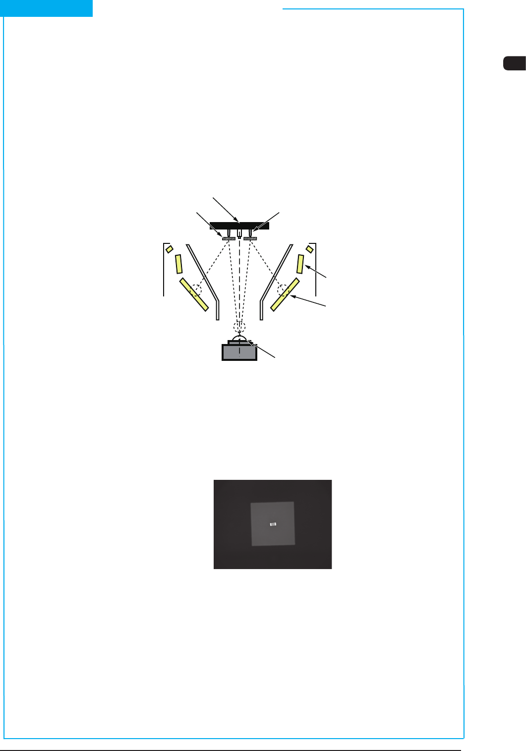
(1) Front Lighting Recognition System
The gure below shows the sectional view of the recognition section in the
front recognition system and the ow of the lights for the recognition.
An appropriate lighting mode (by using the 1, 2, or 3 lamp as front lighting) is
determined for component recognition.
Vacuum nozzle
Components
Back Lighting
Front Lighting 3
(BGA Lighting)
Front Lighting 1
Front Lighting 2 (Coaxial Lighting)
CCD Camera
Scope
Diffusion Plate
F1A24
The lights emitted from the 1, 2, or 3 lamps for front lighting meet the bottom
surface of the component.
The reected lights go into the CCD camera through the monocular. That is,
the CCD camera captures the leads, etc., of the component.
Example : Captured Image for Recognition
F1A25
Short Appendix : Principle of Component Recognition