1OM-1626-001_w.pdf - 第198页
1OM-1610 5-17 1. Specications : Chap.5 091 1-001 Item Description 33. PCB Replacement T ime Dual Transfer Mode Single Transfer Mode Asynchronous Mode Synchronous Mode 0 second Note Within 2 seconds (260 mm or less in PC…
1OM-1610
5-16
1. Specications : Chap.5
0911-001
Item Description
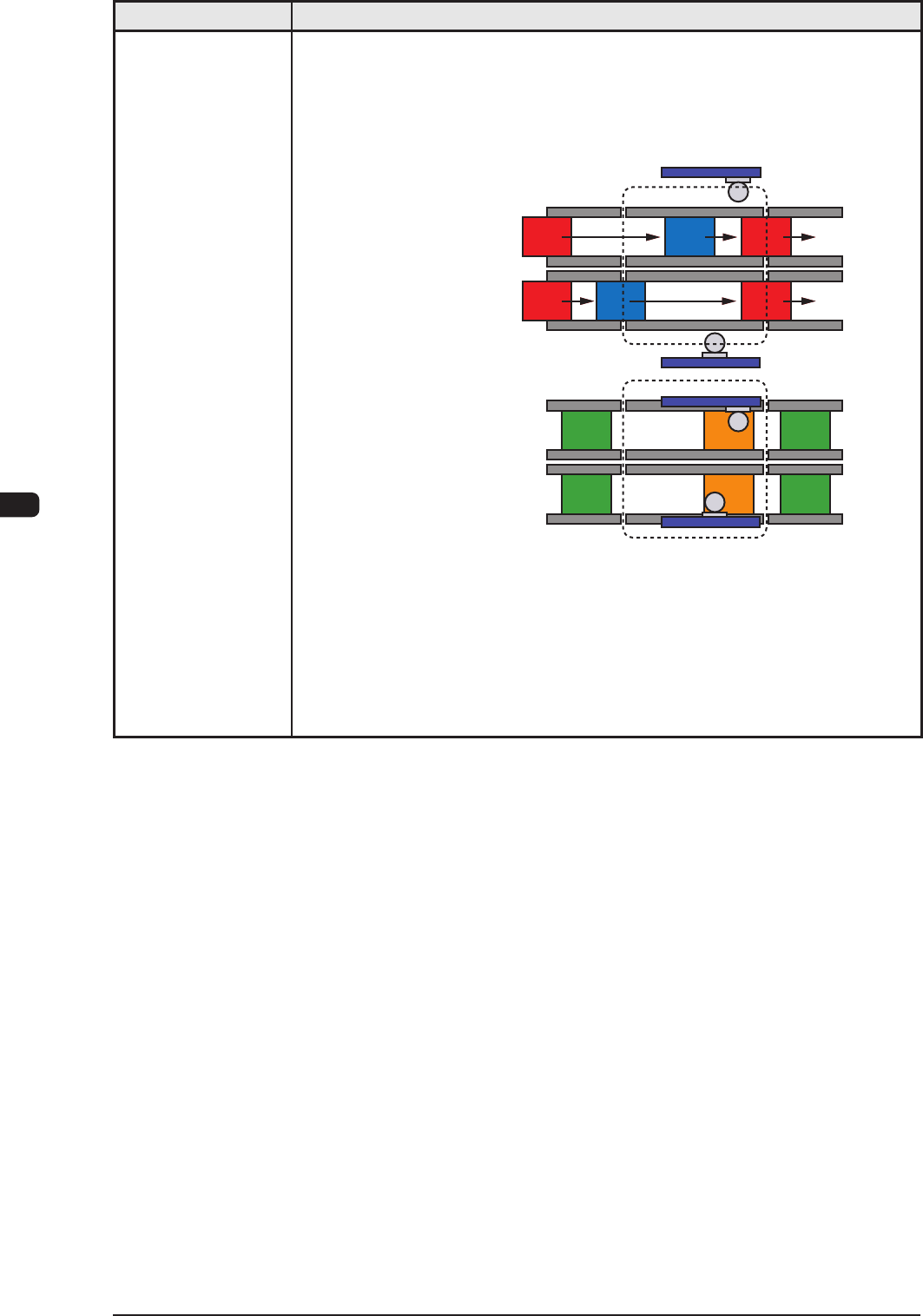
• Synchronous Mode
[Outline of Actions]
The machine starts component placement simultaneously with a PCB being
positioned properly on each transfer lane. When component placement is
completed on both PCBs, both PCBs are discharged at the same time.
Lane A : Transfer
Lane B : Transfer
Lane A : Placement
Lane B : Placement
Process Position
Process Position
After both PCBs are positioned in place, the
machine starts component placement.
After component placement is completed,
PCBs are discharged.
This synchronous mode is used to produce different PCBs (different models)
such as simultaneous component placement on the front and back sides of one
PCB, simultaneous component placement on main and sub PCBs, etc.
T1E1-16
1OM-1610
5-17
1. Specications : Chap.5
0911-001
Item Description
33. PCB
Replacement
Time
Dual Transfer Mode Single Transfer Mode
Asynchronous Mode Synchronous Mode
0 second
Note
Within 2 seconds (260 mm or less in PCB length)
Note:
When "Operation Mode 1" is selected, the transfer time becomes as if it
were "0" (zero) because PCBs are transferred alternately on both lanes
34. Transfer Height 905 mm (Transfer Reference Height)
Note:
As for SMEMA height, another option is required.
35. Au
tomatic Setup
Function
• Automatic Width Setup Function
Standard Design with T
wo Modes; Dual Transfer Mode and Single Transfer
Mode
• Backup Up/Down Function
Standard Design with Divided Type for Dual Transfer
• Support Pin Change
Standard Design with the Support Pin Automatic Setup Function
36. Pattern Program
Asynchronous
In O
peration Mode 1, PCBs are transferred alternately through asynchronous
actions. Therefore, the pattern programs shall be prepared individually for
each PCB transfer lane.
Synchronous
In Operation Mode 2, PCBs are transferred through synchronous actions.
Therefore, it may be necessary to prepare pattern programs in which two
PCBs should be regarded as one PCB in relation to the PCBs on both lanes
and pattern programs that should be used independently for each lane.
Note :
These pattern programs are used according to the results of optimization
on production PCBs.
37. Hardware
Signal Connection for Input and Output Machines
Two types of I/F systems are provided independently for both input and
output machines. Signal paths (paths for signals from/to the input & output
mach
ines and the furnace) can be connected to the I/F board of the input and
output machines.
Signal Connections in Dual and Single Modes
Dual Mode
: 2 Systems
Single Mode : 1 System
38.
Input and Output
Interfaces
Conforming to the specications of the SMEMA communications.
T1E1-17
1OM-1610
5-18
1. Specications : Chap.5
Item Description
39. Others Standard Functions
•
Component Library Teaching Function (GS-TR100)
•
Placement Position
Teaching Function (GS-TZ100)
•
Application for BGA/CSP
(GS-TB100)
•
Automatic Recovery Function for Component Pickup Errors
•
Component Pick-Up Position
Teaching Function
•
Delayed Recovery Function (Recovery Mode)
•
Alternate Component Supply Function
•
Pick-Up and Placement Up/Down-Axis (L-Axis) Control Function
•
Pick-UP
Position (X/Y) Correction Control Function
•
Pocket outline recognition
•
T
wo-stage placement Z-Axis speed reduction
•
Nozzle existence check before pick-up
Dual Function
•
Pattern Program for Dual T
ransfer Mode
The pattern program data preparation, optimization or multi-production
model line balance is performed using the dual transfer system software.
T1E1-18
0911-001