1OM-1626-001_w.pdf - 第80页
1OM-1610 3. Mechanism for Surface Mounting : Chap.1 1-23 091 1-001 3.5.2 Muluti-Functional Head There are three locations for mounting the nozzles on the multi-functional Head and a maximum of three types of nozzle can b…
1OM-1610
1-22
3. Mechanism for Surface Mounting : Chap.1
0911-001
3.5 Placement Head Section
This section is equipped with a mechanism by which the components picked up
by the vacuum nozzles can be placed on the PCB.
A placement head is arranged on each X-axis linear bar (2 heads in total). (2-Beam
2-Head)
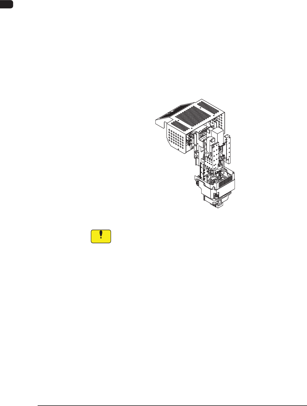
3.5.1 High-speed Head Section
There are fteen locations for mounting the nozzles on the high-speed Head, and
a maximum of fteen types of nozzle can be mounted.
Each head is also provided with a line sensor. The line sensor is used to detect a
component to be picked up and a vertical component. It is also used to measure
the component thickness.
F1A18
Notice
(a) Keep the diffusion plates of the placement heads clear of oil, nicks,
etc. Otherwise, an error may occur during component recognition.
(b) Do not bring any magnetized object such as a magnet close to the
vacuum nozzles.
Otherwise, an error may occur during component picks and
placement.
1OM-1610
3. Mechanism for Surface Mounting : Chap.1
1-230911-001
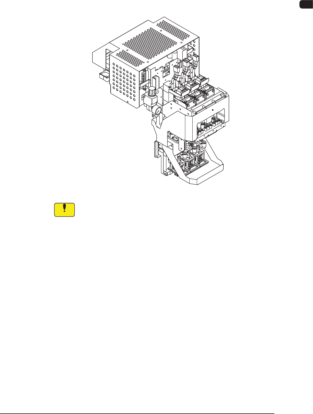
3.5.2 Muluti-Functional Head
There are three locations for mounting the nozzles on the multi-functional Head
and a maximum of three types of nozzle can be mounted to pick up the multi-
functional components.
F1A19
Notice
(a) Keep the diffusion plates of the placement heads clear of oil, nicks,
etc. Otherwise, an error may occur during component recognition.
(b) Do not bring any magnetized object such as a magnet close to the
vacuum nozzles.
Otherwise, an error may occur during component picks and
placement.
1OM-1610
1-24
3. Mechanism for Surface Mounting : Chap.1
0911-001
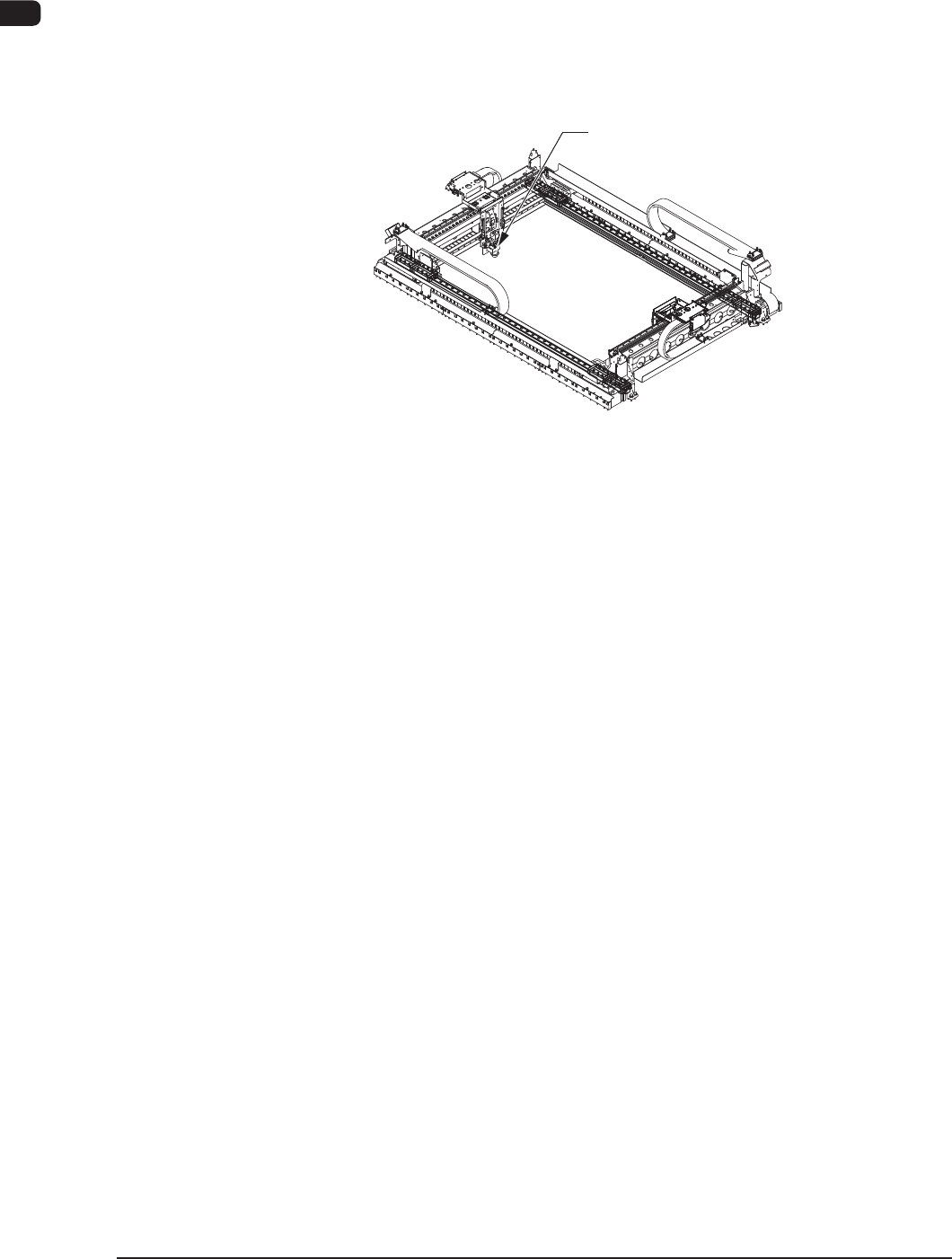
3.6 PEC Recognition Section
Each beam is equipped with a PEC recognition camera and a light source for
illumination, making a pair with the placement head.
The PEC recognition camera is used to detect the ducial marks on a PCB and
the amount of the positional deviation from the ducial mark coordinate data is
calculated to automatically correct the position of a component to be placed.
PEC Recognition Camera
F1A20
The main functions of the PEC recognition section are to detect the position
of a ducial mark and determine the shape of the component. In addition to
those functions, this section works to detect the position of a feeder and make a
positional correction of the captured y image.