1OM-1626-001_w.pdf - 第95页
1OM-1610 1-38 4. Surface Mounting Mechanism : Chap.1 091 1-001 4.1.8 PCB Output The PCB where the components have already been placed is sent to the output machine through the buffer. Note When the out-of-standard output…
1OM-1610
4. Surface Mounting Mechanism : Chap.1
1-370911-001
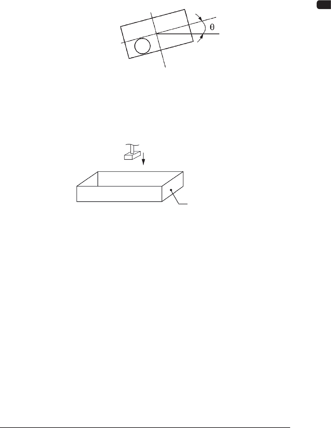
Recognition Correction (Angular Correction)
The picked component is adjusted to the angle (placement direction) of placement
specied in the pattern program by rotating the head. At this time, the angular
deviation (
q
) detected through component recognition is also corrected.
F1A32
Component Discharge (Component Storage Box)
When a recognition error occurs during the component recognition, the placement
head moves to the component storage box and discharges the error-caused
component.
Component Storage Box
Component Discharge F1A33
4.1.7 Component Placement
The placement head moves to the point (the coordinates for the placement)
specied in the pattern program for the PCB in the standby mode in the PCB
positioning section. At this time, the positional deviations (X, Y) measured
through the component recognition are adjusted correctly for proper component
picks.
The lowest limit of the vacuum nozzle is controlled according to the component
library data.
The solenoid valve closes and the component picked up by the vacuum nozzle is
placed on the PCB.
The front and rear beams take component placement and pickup actions repeatedly
in turns, realizing efcient and continuous component mounting.

1OM-1610
1-38
4. Surface Mounting Mechanism : Chap.1
0911-001
4.1.8 PCB Output
The PCB where the components have already been placed is sent to the output
machine through the buffer.
Note
When the out-of-standard output method is used and the PCB transfer speed is
lower in the output machine, set the same transfer speed for the machine as that
in the output machine.
Otherwise, the PCB might be caught in the conveyor position Y arranging
operation.
Set the "Output Machine Set Transfer Speed (Default Value: 300 [mm/sec])" to
the same value in the output machine on the "PCB Transfer Mode Setup".
Reference
Refer to "3.1.3 PCB Transfer Mode Setup" in "Chapter 2 (Volume 3)" for details.

1OM-1610
5. Various Functions : Chap.1
1-390911-001
5. Various Functions
5.1 PEC Recognition Function
In normal cases, two ducial marks are put on a PCB and the coordinate data and
positional deviations are detected by the PEC recognition camera. This function
automatically corrects placement positions of components according to the
recognized positional deviations.
There are three kinds of PEC recognition functions - "Global", "Image", and
"Local". The global recognition function covers all positional deviations over one
PCB and is used to correct them. The image recognition function is used to correct
positional deviations for each individual patterns. The local recognition function
is used to correct positional deviations for each component placement point.
Note
(a) When PCBs are positioned on the PCB positioning section and
mechanical accuracy in PCB positioning varies due to variation in
outer dimensions of PCBs, the PEC recognition function can work
effectively to reduce such inaccuracy.
(b) Fiducial marks are put to detect the position of placement patterns.
Therefore, the positional relation between ducial marks and placement
patterns must be constant. Otherwise, the placement accuracy cannot be
improved.
5.2 Functions related to Component Picks and Placement
5.2.1 Automatic Feeder Axis Adjustment Function
When a component is picked up by the vacuum nozzle and shifted from the
correct pick-up position, this function uses the recognition system to correct the
deviations for accurate component placement. By feeding the recognized amount
of correction back to the pickup position, the pickup position can also be brought
close to the specied one.
5.2.2 Pickup Position Automatic Teaching Function
When a tape feeder is pulled out or inserted, the feeder position is automatically
recognized and the recognized position is fed back to the pickup position data,
making it possible to bring the pickup position as close to the accurate (specied)
one as possible.