1OM-1626-001_w.pdf - 第83页
1OM-1610 1-26 3. Mechanism for Surface Mounting : Chap.1 091 1-001 3.8 Cart Installation Section The cart installation section is equipped with a mechanism by which the bank feeder change cart is setup. The components ar…
1OM-1610
3. Mechanism for Surface Mounting : Chap.1
1-250911-001
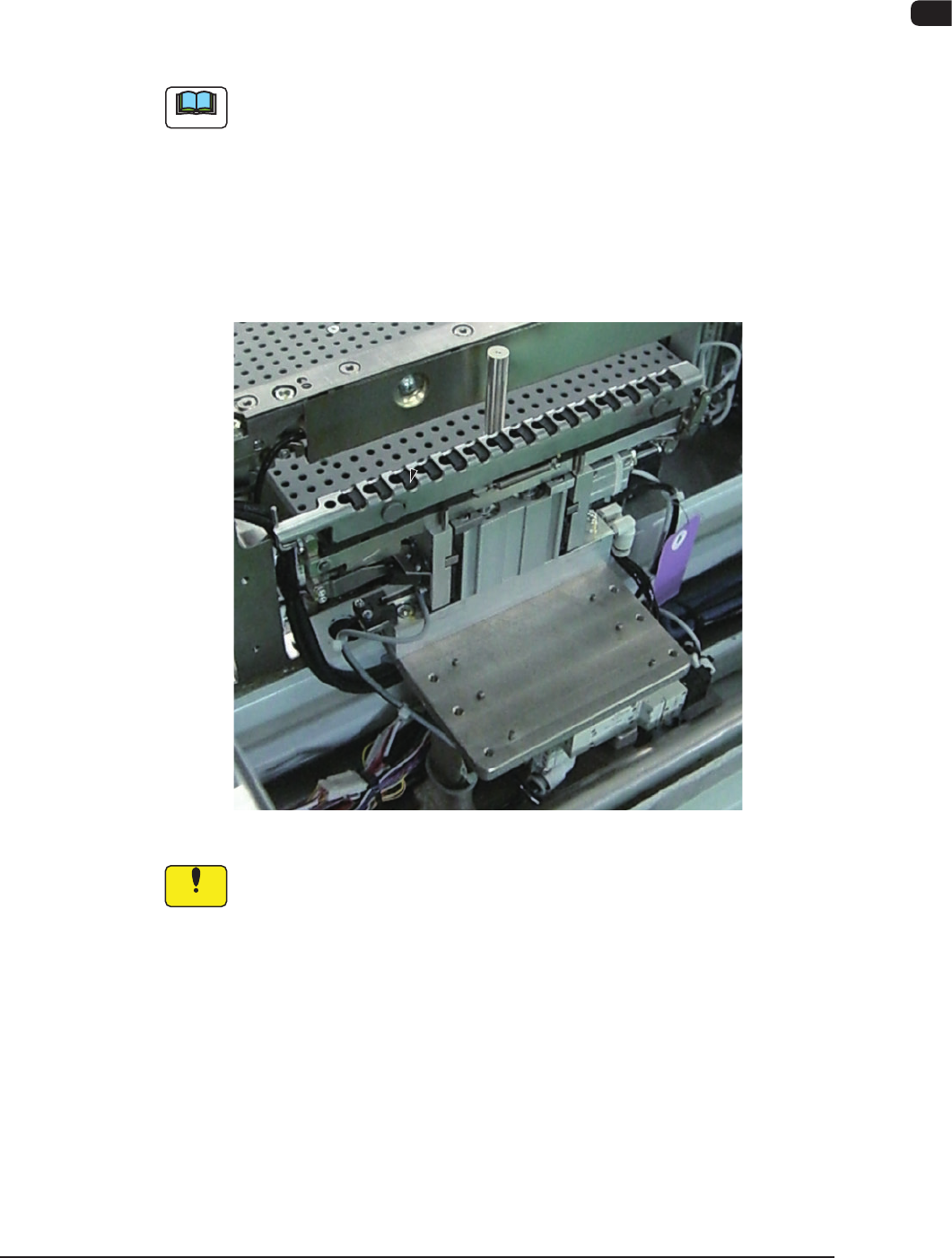
3.7 Nozzle Stocker (Housing) Section
This section is equipped with a mechanism by which the vacuum nozzles can be
stored.
A placement head moves to the area above the nozzle stocker according to the
pattern program and picks up a vacuum nozzle or puts it back in place.
Note
(a) There are three types; the high-speed nozzle stocker, nozzle stocker for
nozzles with multi-functional heads, and the nozzles for middle size
irregular shaped components (option). They are used depending on the
vacuum nozzle type to be used.
(b) Each block can be provided with two nozzle stockers for the high-speed
nozzle stocker, or only one nozzle stocker for the multi-functional nozzle
stocker (standard specication). Two or more nozzle stockers can be
installed on each block (optional specications).
Nozle Stocker (Appearance) F1A21
Notice
(a) Do not put any foreign object in the nozzle stocker section.
Otherwise, the machine will break down.
(b) Do not bring any magnetized object such as a magnet close to the
vacuum nozzles.
Otherwise, an error may occur during component picks and
placement.

1OM-1610
1-26
3. Mechanism for Surface Mounting : Chap.1
0911-001
3.8 Cart Installation Section
The cart installation section is equipped with a mechanism by which the bank
feeder change cart is setup. The components are supplied from the tape feeder
attached onto the feeder base in the bank feeder change cart.
Each feeder base is provided with a "Fdr No." plate that indicates where to
allocate the feeders.
When a component shortage error is generated or a feeder has trouble and the
components cannot be picked up subsequently, the alternative feeder slot No. is
selected to continue the automatic operation. (Feeder Alternate Operation).
In this case, another slot No. across the front and rear beams can be selected.
CAUTION
When a tape feeder is attached or detached, be sure
not to drop it.
Otherwise, a foot injury will result or the feeder itself may
be damaged.
Carefully handle each feeder one by one and do not drop
any.
NOTICE
Do not bring any magnetized object such as a
magnet close to the vacuum nozzles.
Otherwise, an error may occur during component picks
and placement.
When the feeder clamp holding bar is locked (Feeder
Ready Switch turned ON), the tape feeder can not
bexedsecurelyattherearend.
1OM-1610
3. Mechanism for Surface Mounting : Chap.1
1-270911-001
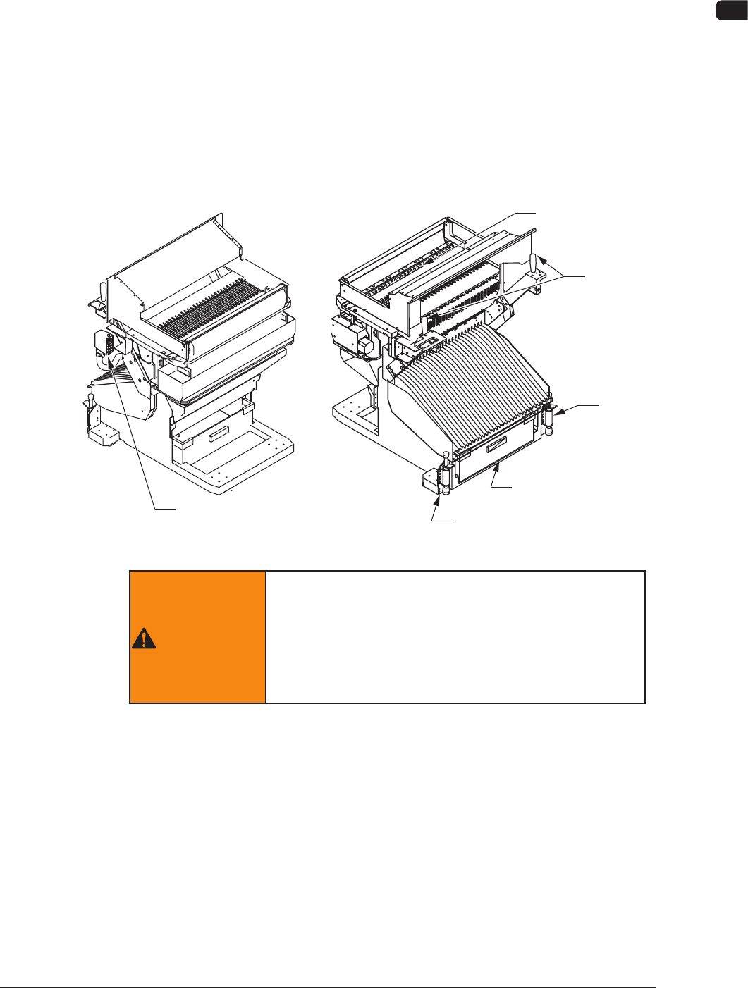
3.8.1 Bank Feeder Change Cart
The bank feeder change carts are used to install the feeder base to the main body
of the machine.
By using a bank feeder change cart, it becomes possible for the whole body of the
feeder base to be replaced with another one at a time.
When the feeders are prepared on the spare cart, a bank feeder change cart can
easily be replaced with the spare one, greatly shortening the time of a model
change operation (feeder replacement).
The bank feeder change cart is equipped with a scrap box that can be used to
collectively dispose the tape chips that were cut off when components were
supplied from the tape feeders.
Feeder Base
Handle
Stopper
Scrap Box
Stopper
Connector
F1A22
WARNING
If the bank feeder change cart is not set, a clearance
will be left at the feeder setting area and the operator
will be exposed to danger.
Be sure to use the machine with the bank feeder
change carts being attached.