1OM-1626-001_w.pdf - 第187页
1OM-1610 5-6 1. Specications : Chap.5 091 1-001 Item Description 1 1. Component Placeable Range Unit : mm Notes : (a) The above gure shows that the vacuum nozzles are not protruding from the outer shapes of components.…
1OM-1610
5-5
1. Specications : Chap.5
0911-001
Item Description
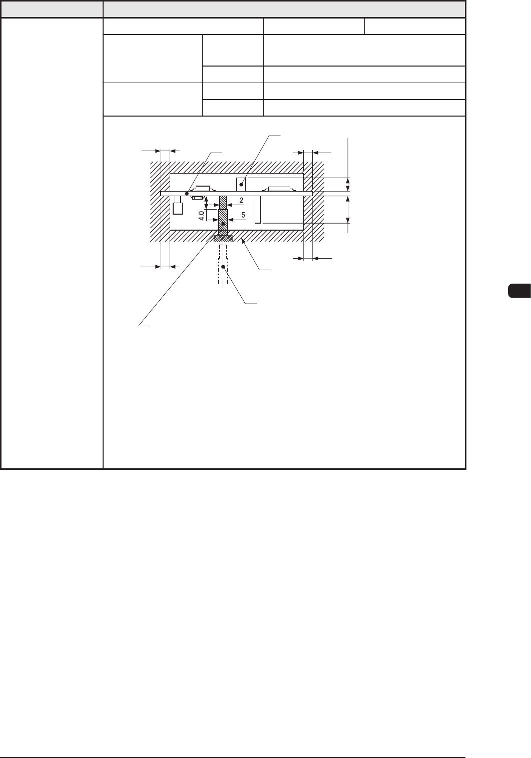
10. Conditions of
PCB before
Placement
(Regulation
of Component
Height)
Dual Mode Single Mode
Height of
Previously-Placed
Component
Upper Surface
12.7 mm / High-Speed Head
25.4 mm / Multifunctions Head
Lower Surface
30 mm
Dead Space
Upper Surface
3.0 mm
Lower Surface
3.0 mm
3.0
3.0
φ
φ
3.0
3.0
PCB
Component
(Front Side of Machine)
Previously-placed
Components Unallowed
Range
PCB Support Pin (At this position
when PCB is transfered.)
PCB Support Pin (Several Places)
Max. 30.0
When the High-Speed
Head is used:
Max. 12.7
When the Multi-Functional
Head is used:
Max. 25.4
Unit : mm
Notes
: (a) PCB support pin position can be moved "10mm" by "10mm" .
(b) Set the PCB support pin on the position where it does not touch
the already placed component.
(c) The gure shows that the PCB is being supported.
(d) The dimensions are those for design reference.
Leave some room for the actual setting.
T1E1-5
1OM-1610
5-6
1. Specications : Chap.5
0911-001
Item Description
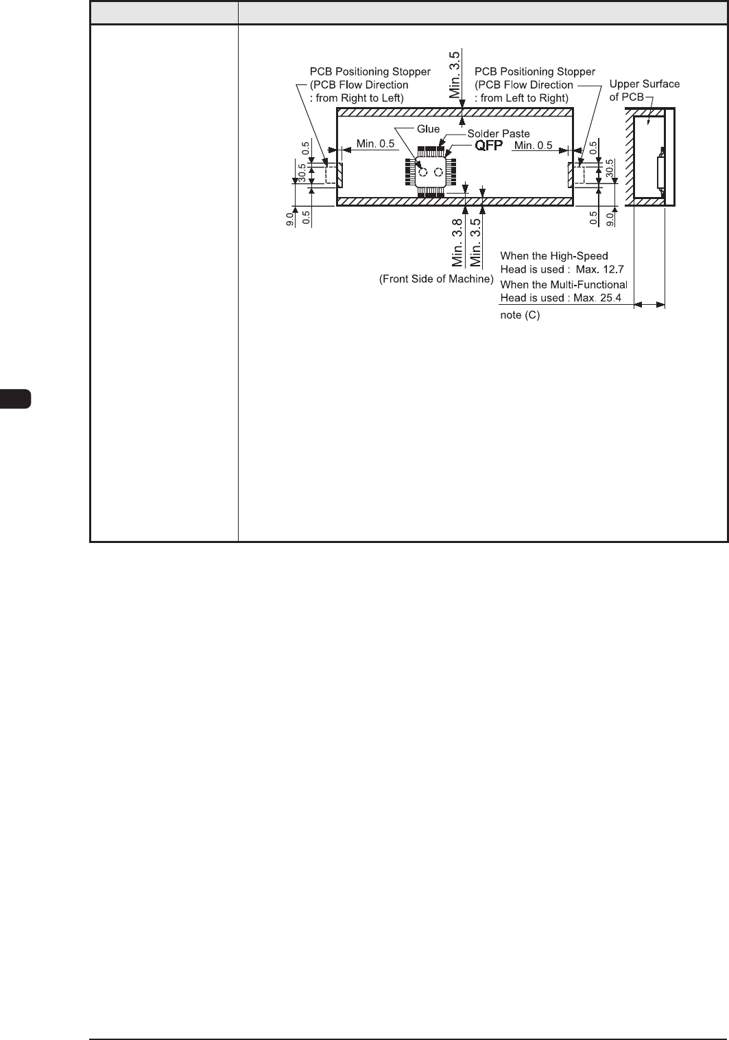
11. Component
Placeable Range
Unit : mm
Notes :
(a) The above gure shows that the vacuum nozzles are not
protruding from the outer shapes of components.
(b) Comp
onents cannot be placed in the shadowed area.
Components cannot be placed in the range (0.5 mm) around the
opening such as a hole.
(c)
This size is the max. possible placement height including the
placed component height from the PCB.
T1E1-6
1OM-1610
5-7
1. Specications : Chap.5
0911-001
Item Description
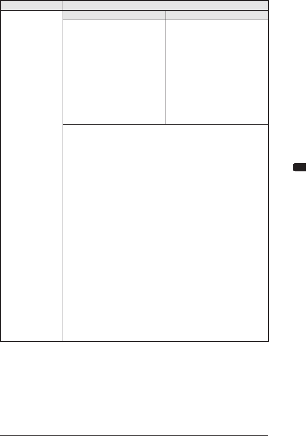
12. Applicable
Components
High-Speed Head Multi-Functional Head
(1) Applicable Components
Size : 0.4
×
0.2 to 44
×
44 mm
Thickness
: Max. 12.7 mm
Lead Pitch : 0.3 mm pitch or
more
Lead Width : Min. 0.1 mm
Lead Length
: Min. 0.20 mm
Note :
Some components
cannot be used due to the
mechanical characteristics,
shapes, etc.
(1) Applicable Components
Size : 1.0
×
0.5 to 55
×
55 mm
Thickness
: Max. 25.4 mm
Lead Pitch : 0.3 mm pitch or
more
Connector : Max. 100
×
26 mm
Note :
Some components
cannot be used due to the
mechanical characteristics,
shapes, etc.
Applicable Components for Reference
•
Cylindrical Components
Resistors, Capacitors, Diodes, and Other similar-shaped components
•
Square Components
Resistors, Film Capacitors, Coils, Chip Ceramic Filters, and Other
similar-shaped components
•
Deform Components
Semi-Fixed V
ariable Resistors, Trimmer Capacitors, and Other similar-
shaped components
•
ICs
Mini-Flat ICs, Plastic Chip Carrier with Leads, and Other similar-shaped
components
•
Leaded Components
Mini-Mold T
ransistors, Mini-Power Transistors, Filters, LEDs, Diodes,
Coils, Tantalum Capacitors, Aluminum Electrolytic Capacitors, and Other
similar-shaped components
•
Connectors
Connectors for FFC / FPC, PCB-to-PCB Connectors, Wire-to-PCB
Connectors, PLCC Sockets, and Other Similar
-Shaped Components
•
BGA/CSP Components (Option)
BGA, CSP, LGA, and Other Similar
-Shaped Components
Size
: Max. 44
×
44 mm
Ball Diameter
: Min.
φ
0.13 mm
Ball Pitch
: 0.25 mm pitch or more
T1E1-7