1OM-1626-001_w.pdf - 第204页
1OM-1610 5-23 1. Specications : Chap.5 1.4 Fiducial Marks (1) T ype and Size Mark Type D1 [mm] D2 [mm] Remarks Round 0.3 to 3.0 0 to 2.8 (D1 - 0.2 = > D2) • Mark Reference : Center Size of a punched hole Square 0.3 t…
1OM-1610
5-22
1. Specications : Chap.5
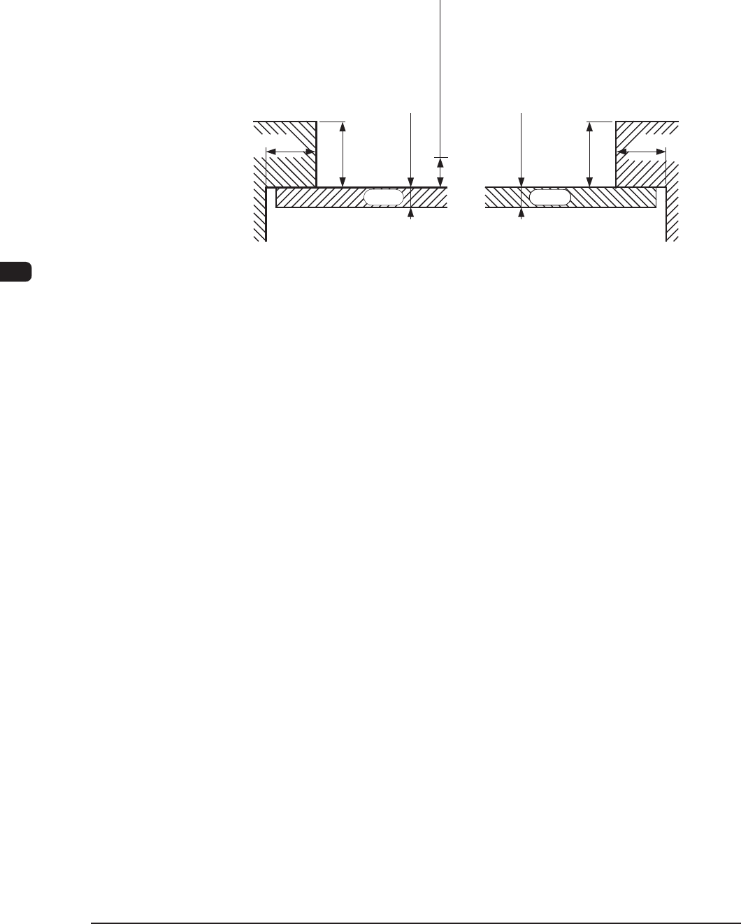
(3) Limit of Closest Distance to Obstacle
•
The closest distance between an obstacle (See each sectional view.) and
the vacuum nozzle or component should be 0.5 mm or more. The upper
surface of the PCB is the reference plane.
0.3 to 5.0
0.3 to 5.0
3.0
2.0
3.0
2.0
0.5 mm or more
PCB PCB
(Rear Side of Machine)(Front Side of Machine)
Limit of Closest Distance
Unit : mm
Section View of Chute F1E2
0911-001
1OM-1610
5-23
1. Specications : Chap.5
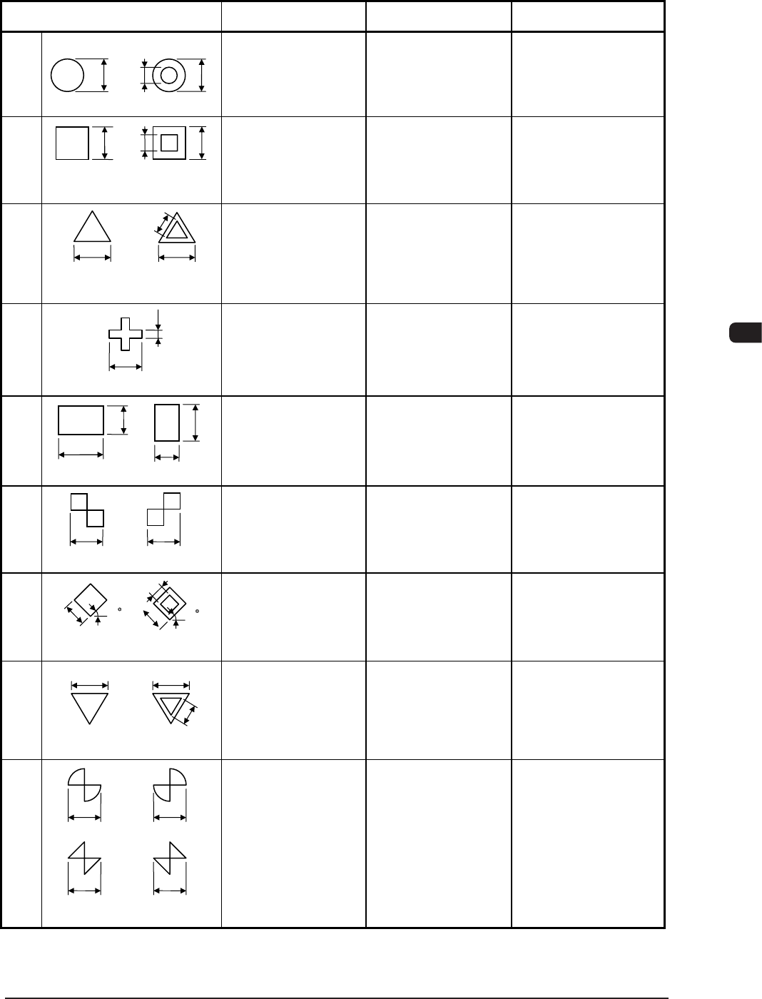
1.4 Fiducial Marks
(1) Type and Size
Mark Type D1 [mm] D2 [mm] Remarks
Round
0.3 to 3.0 0 to 2.8
(D1 - 0.2 = > D2)
• Mark Reference :
Center
Size of a punched
hole
Square
0.3 to 3.0 0 to 2.8
(D1 - 0.2 = > D2)
• Mark Reference :
Center of Gravity
• D2 :
Size of a punched
hole
Equilateral
Triangle
(Upturned)
0.5 to 3.0 0 to 2.8
(D1 - 0.2 = > D2)
• Mark Reference :
Center of Gravity
• D2 :
Size of a punched
hole
Cross
0.5 to 3.0 0.2 to 1.5
(D1/2 = > D2)
• Mark Reference :
Center of Gravity
Rectangle
0.5 to 3.0 0.5 to 3.0
• Mark Reference :
Center of Gravity
Checker
(Square)
0.5 to 3.0
−
•
Mark Reference :
Contact of Two
Squares
Diamond
(Rotated Square)
0.5 to 3.0 0 to 2.8
(D1 - 0.2 = > D2)
• Mark Reference :
Center of Gravity
• D2 :
Size of a punched
hole
Equilateral
Triangle
(Downturned)
0.5 to 3.0 0 to 2.8
(D1 - 0.2 = > D2)
• Mark Reference :
Center of Gravity
• D2 :
Size of a punched
hole
Bow Tie
0.5 to 3.0
−
•
Mark Reference :
Contact of Two
Fan Shapes or
Triangles
D2
D1
D1
D1
D2
D1
(Front Side of Machine)
D2
D1
(Front Side of Machine)
(Front Side of Machine)
D1
D2
D2
D1
(Front Side of Machine)
D1
D1
D1
D2
D1
(Front Side of Machine)
Or
D1
D1
D1
Or
D1
(Front Side of Machine)
(Front Side of Machine)
D2
D1
D1
D1
45°
D2
D1
(Front Side of Machine)
45°
D2 :
•
T1E4-1
0911-001
1OM-1610
5-24
1. Specications : Chap.5
Mark Type D1 [mm] D2 [mm] Remarks
Checker
(Rectangle)
0.5 to 3.0 0.5 to 3.0
• Mark Reference :
Contact of Two
Rectangles
Through Hole
(Round)
0.5 to 3.0 0.5 to 1.5
• Mark Reference :
Center
• D2 :
Size of a punched
hole
• W : Min. 0.25 mm
Pad Mark
(Rectangular)
0.5 to 3.0 0.5 to 2.0
• Mark Reference :
Center of Gravity
D1
D2
D1
D2
D1
D2
D1
D2
Or Or
(Front Side of Machine)
D2
D1
W
(
Front Side of Machine
)
D2
W
D1
Note : b
(Front Side of Machine)
D2
D1
D1
D2
Note : b
T1E4-2
Note
(a) The error of the mark size should be within ± 10 % by comparison with the
reference pattern.
(b) A through hole or a pad mark should have only one land which is directed
in increments of 45°.
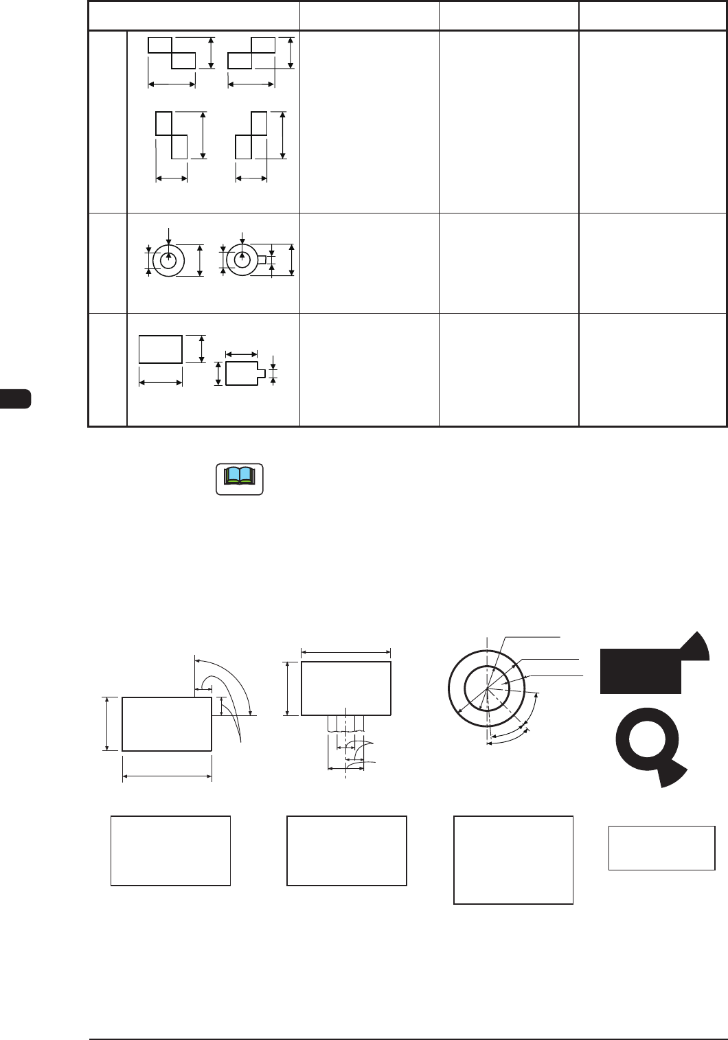
(2) Specications of Line extended from a Pad Mark or a Through Hole.
(See below)
1/3 of Side
Range of Tangent
Lines related between
Pad Mark and Land
(Front Side of Machine)
(Front Side of Machine)
0.5 to 2.0
0.5 to 3.0
0.5 to 2.0
0.5 to 3.0
Range of Tangent
Lines related between
Pad Mark and Land
(Front Side of Machine)
(Range of Tangent
Lines related between
Pad Mark and Land)
(Front Side of Machine)
0.5 to 1.5
1.0 to 3.0
45°
Examples of
Land Locations
Range of Land
Location for
Through Hole
(45° at the bottom
right of the hole)
Range of Land
Location in
Increments of 90°
for Pad Mark
Range of Land
Location in
Increments of 45°
for Pad Mark
Min. 0.25
40°
1/3 of Side
40°
Unit : mm
F1E3
0911-001