1OM-1626-001_w.pdf - 第195页
1OM-1610 5-14 1. Specications : Chap.5 091 1-001 Item Description 31. T ransfer Modes When the PCB size is 216 mm or less, the dual transfer mode can be selected. In the dual transfer mode, two transfer lanes are used. …
1OM-1610
5-13
1. Specications : Chap.5
0911-001
Item Description
24. Environmental
Condition
Temperature : 20
±
10
°
C
Humidity : 30 to 80 % (Avoid dew condensation)
Note :
When the ambient temperature rises more than the surface of the
machine, dew condensation might occur under the condition described
below.
Note that dew condensation may cause the machine to break down.
Condition of Dew Condensation
Dew condensation might occur when the difference (based on
"Humidity (%)") between the ambient and surface temperatures of the
machine reach the values or more in the table below
.
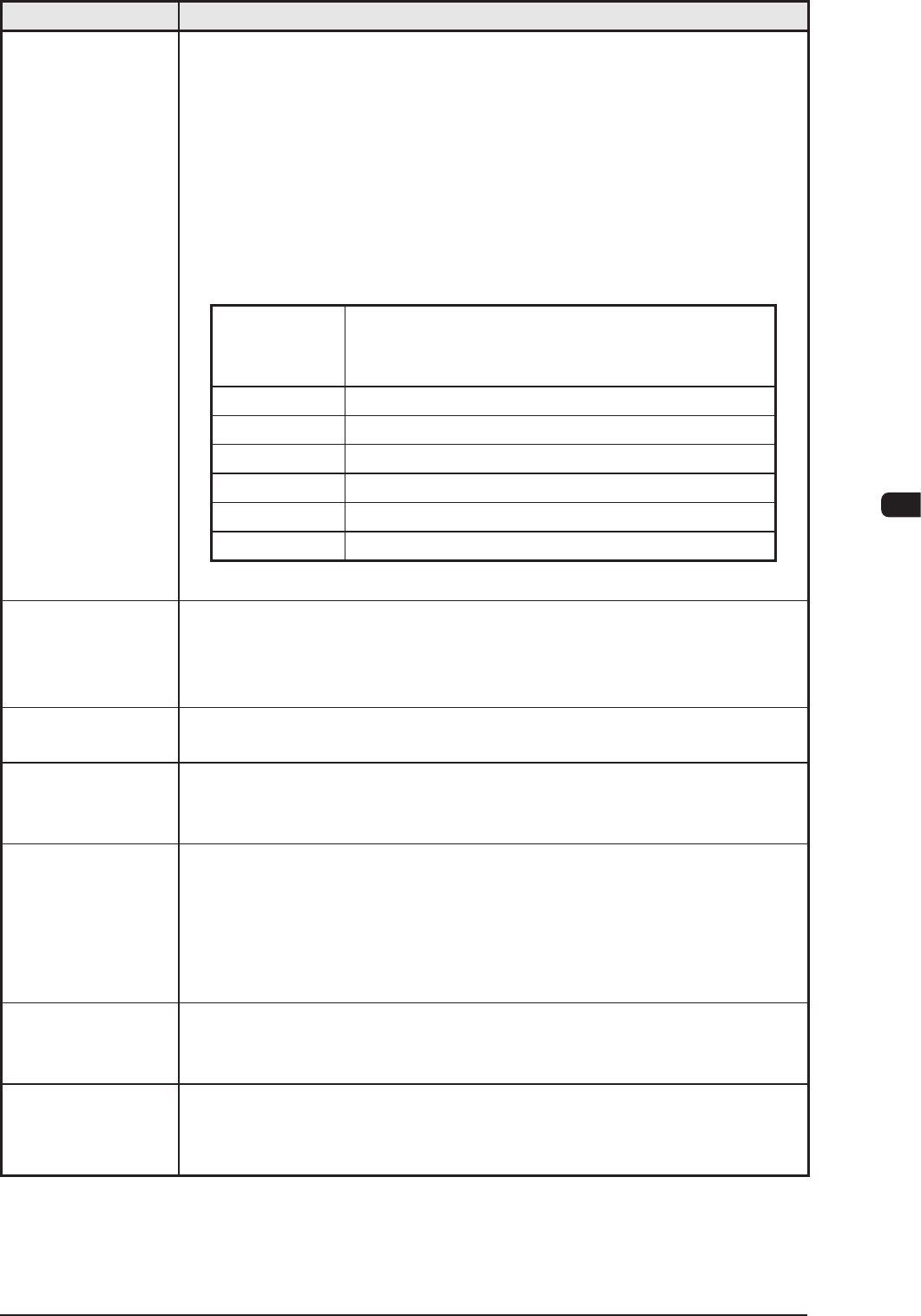
Humidity (%)
Differences between Ambient and Surface
Temperatures of Machine
(Ambient Temperature > Surface Temperature)
80 3
°
C or more
70 6
°
C or more
60 8
°
C or more
50 10
°
C or more
40 14
°
C or more
30 18
°
C or more
25. Power Supply 200
±
20 V AC, 3-Phase, 50/60 Hz
Connected to the power supply unit (3-phase 3-wire system)
(The grounding cable should be connected to the PE terminal).
26. Apparent Power Approx. 6.1 kVA (Max.)
27.
Power
Consumption/
Hour
Approx. 1.22 kWh
28. Dimensions Approx. : 1,280 (Width) mm (Including Input/Output Conveyor)
×
1,900 (Depth) mm
(Including Bank Feeder Change Cart)
×
1,450 (Height) mm
(1,910 mm : Including
Tower)
29. Mass Approx. 1,700 kg
(excluding. the Bank Feeder Change Carts and the tape feeders)
30. Environmental
Requirements
for Bank Feeder
Change Cart
Floor Gradient : 10/1000 or less
Note :
The oor should be hard enough for the casters of the cart to move
smoothly.
T1E1-13
1OM-1610
5-14
1. Specications : Chap.5
0911-001
Item Description
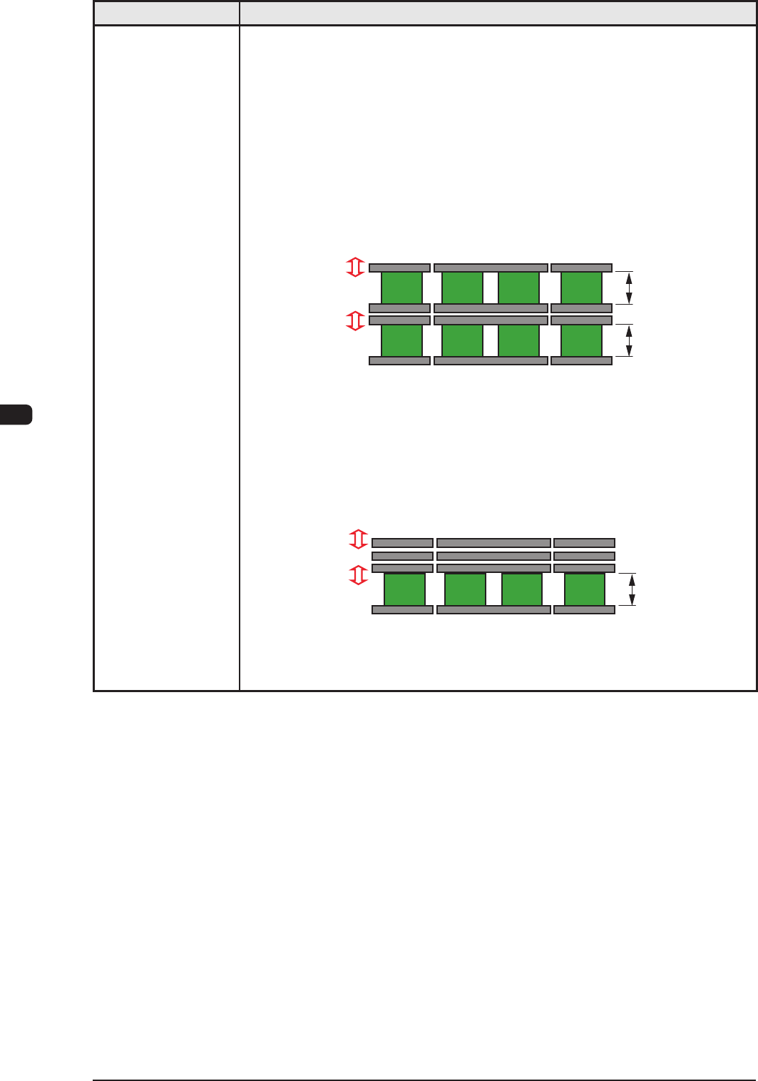
31. Transfer Modes When the PCB size is 216 mm or less, the dual transfer mode can be selected.
In the dual transfer mode, two transfer lanes are used. The single transfer mode
can be selected to transfer the PCBs exceeding 216 mm but not exceeding
381 mm.
When PCBs exceeding 216 mm must be produced, the single transfer mode is
prepared for convenience, making it possible to produce such PCBs.
• Dual
Transfer Mode (Dual Transfer for Two PCBs at the same time)
PCB size 50 mm < Y <= 216 mm: In the case of transferring two PCBs:
The PCBs are transferred using the two lanes as the basic function of the
dual transfer system.
Movable A
Fixed A
Movable B
Fixed B
Front Side of Machine
Buffer Section Buffer Section
Locating L/R Section
Max. 216 mm
Max. 216 mm
• Single Transfer Mode (Dual Transfer for Single PCB)
PCB Size 50 mm <= Y <= 381 mm: In the case of transferring one PCB:
The three rails (Movable A, Fixed A and Movable B) on the rear side are
pushed together to the rear and the single transfer is performed.
Movable A
Fixed A
Movable B
Fixed B
Front Side of Machine
Max. 381 mm
Buffer Section Buffer Section
Locating L/R Section
T1E1-14
1OM-1610
5-15
1. Specications : Chap.5
0911-001
Item Description
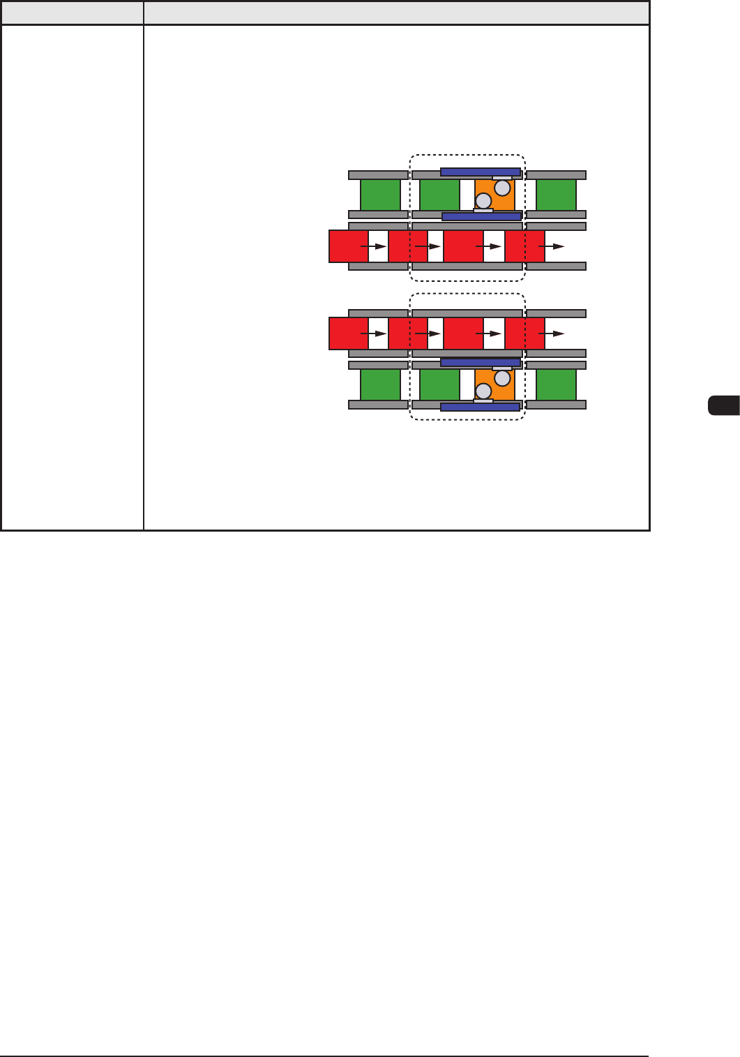
32. Operation Mode
• Asynchronous Mode
[Outline of Actions]
The machine starts component placement on either one (positioned one) of the
PCBs on the two transfer lanes.
After the machine has completed component placement on the PCB on one
lane, it starts placement on the PCB on the other lane.
Lane A : Placement
Lane B : Transfer
Lane A : Transfer
Process Position
Process Position
Lane B : Placement
Since the PCBs are transferred alternately, components are placed on the PCB
on either one of the lanes, making it possible for the machine to continuously
place components regardless of which PCB transfer should take place rst.
Ref.: The PCB transfer time becomes as if it were "0" (zero).
T1E1-15