1OM-1626-001_w.pdf - 第89页
1OM-1610 1-32 3. Mechanism for Surface Mounting : Chap.1 091 1-001 (2) Front Lighting Recognition System (For BGA Components) The gure below shows the sectional view of the recognition section in the front lighting reco…
1OM-1610
3. Mechanism for Surface Mounting : Chap.1
1-310911-001
The back and front lighting recognition systems are prepared for component
recognition. Either one of them is selected automatically according to the
lighting mode specied in the component library data.
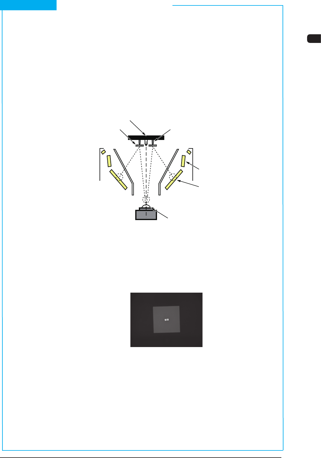
(1) Front Lighting Recognition System
The gure below shows the sectional view of the recognition section in the
front recognition system and the ow of the lights for the recognition.
An appropriate lighting mode (by using the 1, 2, or 3 lamp as front lighting) is
determined for component recognition.
Vacuum nozzle
Components
Back Lighting
Front Lighting 3
(BGA Lighting)
Front Lighting 1
Front Lighting 2 (Coaxial Lighting)
CCD Camera
Scope
Diffusion Plate
F1A24
The lights emitted from the 1, 2, or 3 lamps for front lighting meet the bottom
surface of the component.
The reected lights go into the CCD camera through the monocular. That is,
the CCD camera captures the leads, etc., of the component.
Example : Captured Image for Recognition
F1A25
Short Appendix : Principle of Component Recognition
1OM-1610
1-32
3. Mechanism for Surface Mounting : Chap.1
0911-001
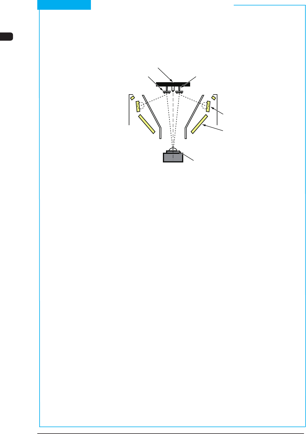
(2) Front Lighting Recognition System (For BGA Components)
The gure below shows the sectional view of the recognition section in the
front lighting recognition system (for BGA components) and the ow of lights
for the recognition.
Vacuum nozzle Components
Back Lighting
Front Lighting 3
(BGA Lighting)
Front Lighting 1
Front Lighting 2 (Coaxial Lighting)
CCD Camera
Scope
Diffusion Plate
F1A26
The light emitted from the lamp for front lighting 3 meets the balls located on
the bottom of the BGA component.
The reected light goes into the CCD camera through the monocular.
The captured image of the balls looks like a doughnut. That is, the CCD
camera captures the image of the balls to determine where the balls are located
or how the balls are arranged (missing balls, etc.).
Short Appendix : Principle of Component Recognition (Continued)
1OM-1610
3. Mechanism for Surface Mounting : Chap.1
1-330911-001
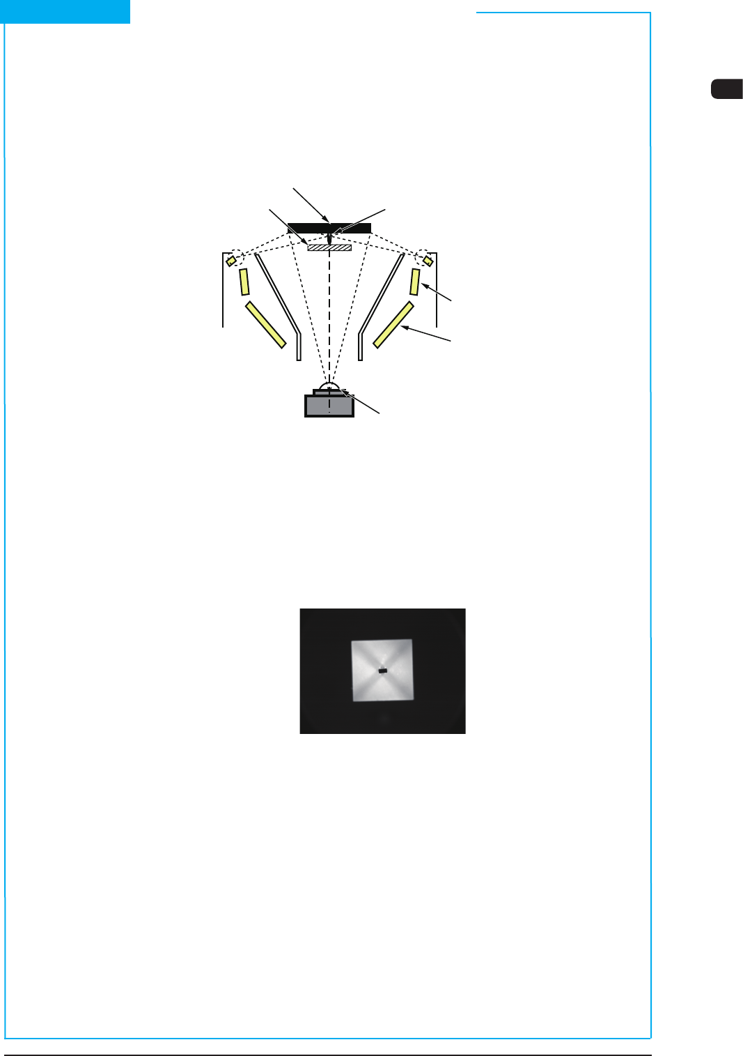
(3) Back Lighting Recognition System
The gure below shows the sectional view of the recognition section in the
back lighting recognition system and the ow of lights for the recognition.
When a component like the shadowed one in the gure is used, the outline of
the component is recognized through the back lighting.
Vacuum nozzle Components
Back Lighting
Front Lighting 3
(BGA Lighting)
Front Lighting 1
Front Lighting 2 (Coaxial Lighting)
CCD Camera
Scope
Diffusion Plate
F1A27
The lights emitted from the lamps for back lighting meet the diffusion plate
and reect to the component.
At this time, the lights that do not meet the component go into the CCD camera
through the monocular.
That is, the CCD camera captures the outline of the component.
Example : Captured Image for Recognition
F1A28
Short Appendix : Principle of Component Recognition (Continued)