1OM-1626-001_w.pdf - 第196页
1OM-1610 5-15 1. Specications : Chap.5 091 1-001 Item Description 32. Operation Mode • Asynchronous Mode [Outline of Actions] The machine starts component placement on either one (positioned one) of the PCBs on the two …
1OM-1610
5-14
1. Specications : Chap.5
0911-001
Item Description
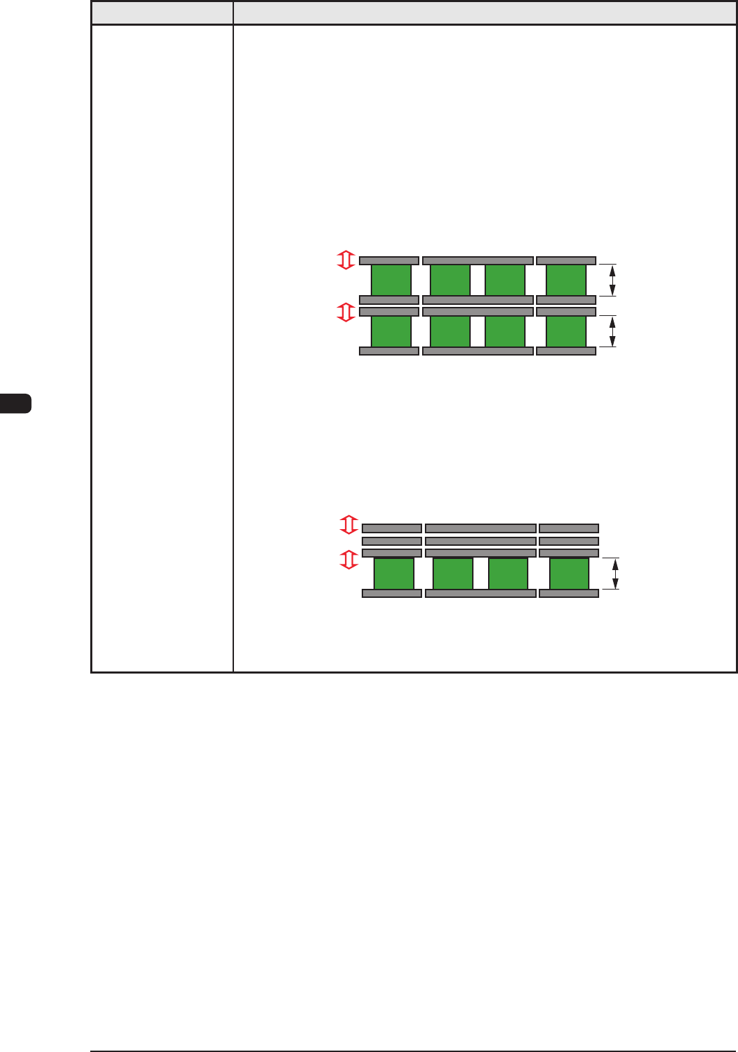
31. Transfer Modes When the PCB size is 216 mm or less, the dual transfer mode can be selected.
In the dual transfer mode, two transfer lanes are used. The single transfer mode
can be selected to transfer the PCBs exceeding 216 mm but not exceeding
381 mm.
When PCBs exceeding 216 mm must be produced, the single transfer mode is
prepared for convenience, making it possible to produce such PCBs.
• Dual
Transfer Mode (Dual Transfer for Two PCBs at the same time)
PCB size 50 mm < Y <= 216 mm: In the case of transferring two PCBs:
The PCBs are transferred using the two lanes as the basic function of the
dual transfer system.
Movable A
Fixed A
Movable B
Fixed B
Front Side of Machine
Buffer Section Buffer Section
Locating L/R Section
Max. 216 mm
Max. 216 mm
• Single Transfer Mode (Dual Transfer for Single PCB)
PCB Size 50 mm <= Y <= 381 mm: In the case of transferring one PCB:
The three rails (Movable A, Fixed A and Movable B) on the rear side are
pushed together to the rear and the single transfer is performed.
Movable A
Fixed A
Movable B
Fixed B
Front Side of Machine
Max. 381 mm
Buffer Section Buffer Section
Locating L/R Section
T1E1-14
1OM-1610
5-15
1. Specications : Chap.5
0911-001
Item Description
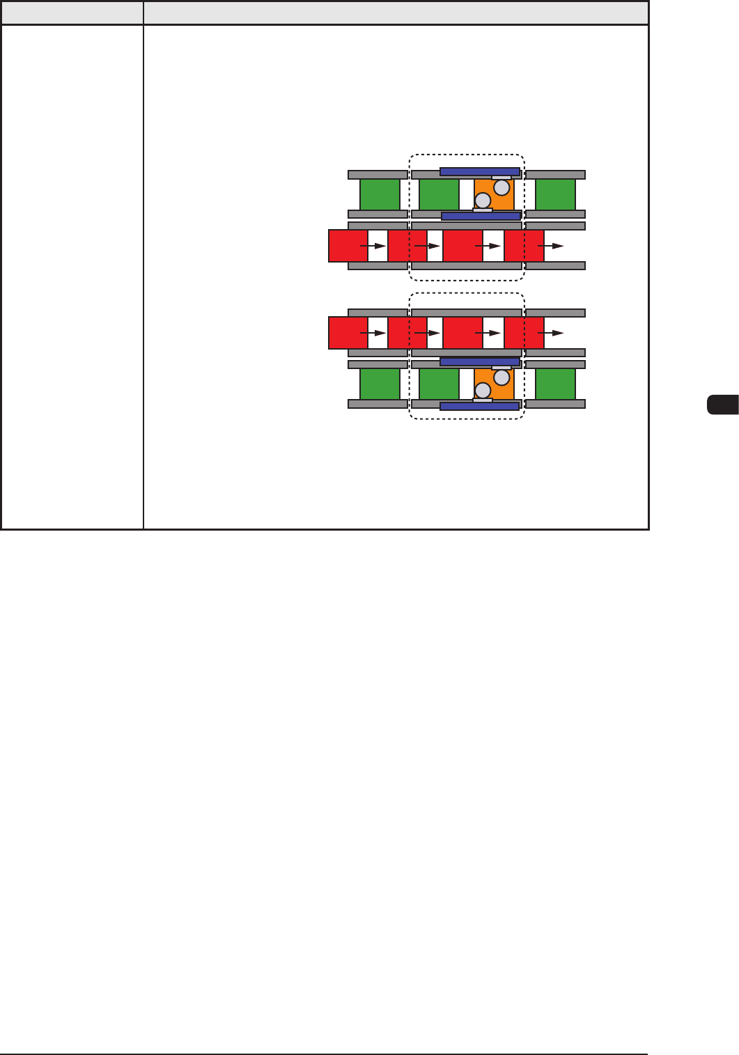
32. Operation Mode
• Asynchronous Mode
[Outline of Actions]
The machine starts component placement on either one (positioned one) of the
PCBs on the two transfer lanes.
After the machine has completed component placement on the PCB on one
lane, it starts placement on the PCB on the other lane.
Lane A : Placement
Lane B : Transfer
Lane A : Transfer
Process Position
Process Position
Lane B : Placement
Since the PCBs are transferred alternately, components are placed on the PCB
on either one of the lanes, making it possible for the machine to continuously
place components regardless of which PCB transfer should take place rst.
Ref.: The PCB transfer time becomes as if it were "0" (zero).
T1E1-15
1OM-1610
5-16
1. Specications : Chap.5
0911-001
Item Description
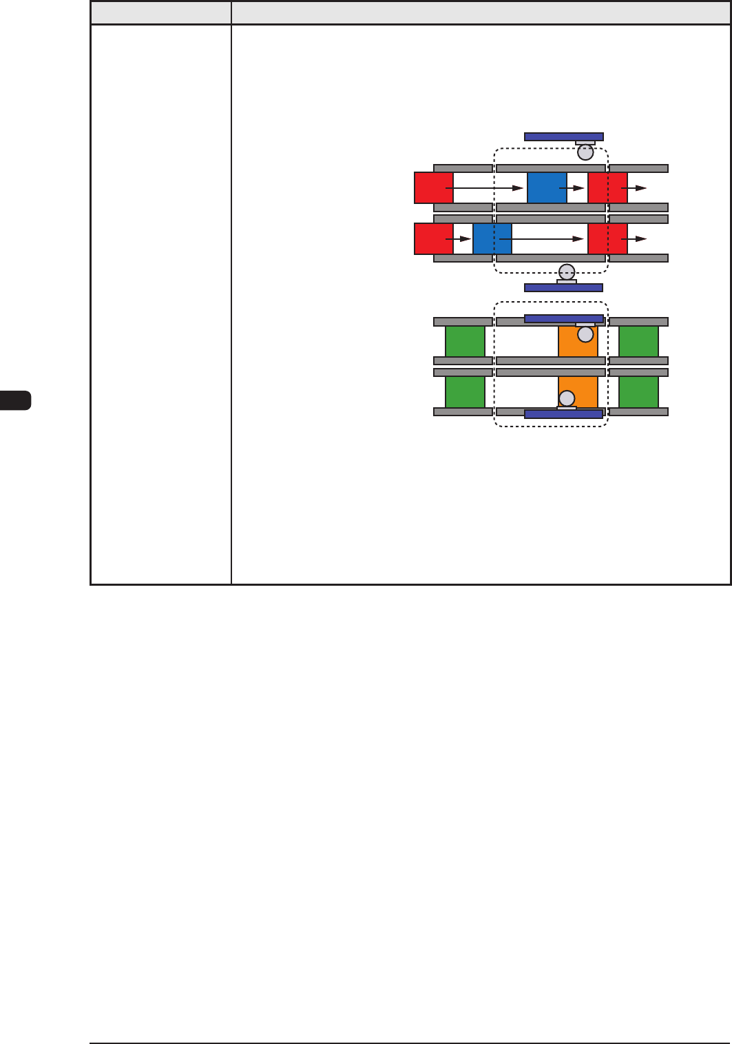
• Synchronous Mode
[Outline of Actions]
The machine starts component placement simultaneously with a PCB being
positioned properly on each transfer lane. When component placement is
completed on both PCBs, both PCBs are discharged at the same time.
Lane A : Transfer
Lane B : Transfer
Lane A : Placement
Lane B : Placement
Process Position
Process Position
After both PCBs are positioned in place, the
machine starts component placement.
After component placement is completed,
PCBs are discharged.
This synchronous mode is used to produce different PCBs (different models)
such as simultaneous component placement on the front and back sides of one
PCB, simultaneous component placement on main and sub PCBs, etc.
T1E1-16