1OM-1626-001_w.pdf - 第199页
1OM-1610 5-18 1. Specications : Chap.5 Item Description 39. Others Standard Functions • Component Library T eaching Function (GS-TR100) • Placement Position T eaching Function (GS-TZ100) • Application for BGA/CSP (GS-TB…
1OM-1610
5-17
1. Specications : Chap.5
0911-001
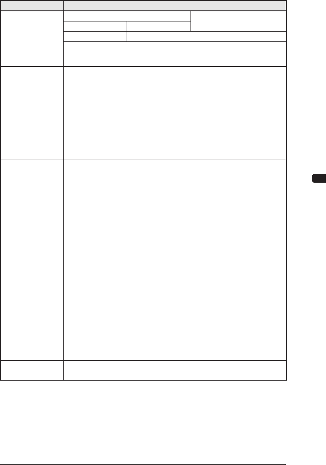
Item Description
33. PCB
Replacement
Time
Dual Transfer Mode Single Transfer Mode
Asynchronous Mode Synchronous Mode
0 second
Note
Within 2 seconds (260 mm or less in PCB length)
Note:
When "Operation Mode 1" is selected, the transfer time becomes as if it
were "0" (zero) because PCBs are transferred alternately on both lanes
34. Transfer Height 905 mm (Transfer Reference Height)
Note:
As for SMEMA height, another option is required.
35. Au
tomatic Setup
Function
• Automatic Width Setup Function
Standard Design with T
wo Modes; Dual Transfer Mode and Single Transfer
Mode
• Backup Up/Down Function
Standard Design with Divided Type for Dual Transfer
• Support Pin Change
Standard Design with the Support Pin Automatic Setup Function
36. Pattern Program
Asynchronous
In O
peration Mode 1, PCBs are transferred alternately through asynchronous
actions. Therefore, the pattern programs shall be prepared individually for
each PCB transfer lane.
Synchronous
In Operation Mode 2, PCBs are transferred through synchronous actions.
Therefore, it may be necessary to prepare pattern programs in which two
PCBs should be regarded as one PCB in relation to the PCBs on both lanes
and pattern programs that should be used independently for each lane.
Note :
These pattern programs are used according to the results of optimization
on production PCBs.
37. Hardware
Signal Connection for Input and Output Machines
Two types of I/F systems are provided independently for both input and
output machines. Signal paths (paths for signals from/to the input & output
mach
ines and the furnace) can be connected to the I/F board of the input and
output machines.
Signal Connections in Dual and Single Modes
Dual Mode
: 2 Systems
Single Mode : 1 System
38.
Input and Output
Interfaces
Conforming to the specications of the SMEMA communications.
T1E1-17

1OM-1610
5-18
1. Specications : Chap.5
Item Description
39. Others Standard Functions
•
Component Library Teaching Function (GS-TR100)
•
Placement Position
Teaching Function (GS-TZ100)
•
Application for BGA/CSP
(GS-TB100)
•
Automatic Recovery Function for Component Pickup Errors
•
Component Pick-Up Position
Teaching Function
•
Delayed Recovery Function (Recovery Mode)
•
Alternate Component Supply Function
•
Pick-Up and Placement Up/Down-Axis (L-Axis) Control Function
•
Pick-UP
Position (X/Y) Correction Control Function
•
Pocket outline recognition
•
T
wo-stage placement Z-Axis speed reduction
•
Nozzle existence check before pick-up
Dual Function
•
Pattern Program for Dual T
ransfer Mode
The pattern program data preparation, optimization or multi-production
model line balance is performed using the dual transfer system software.
T1E1-18
0911-001
1OM-1610
5-19
1. Specications : Chap.5
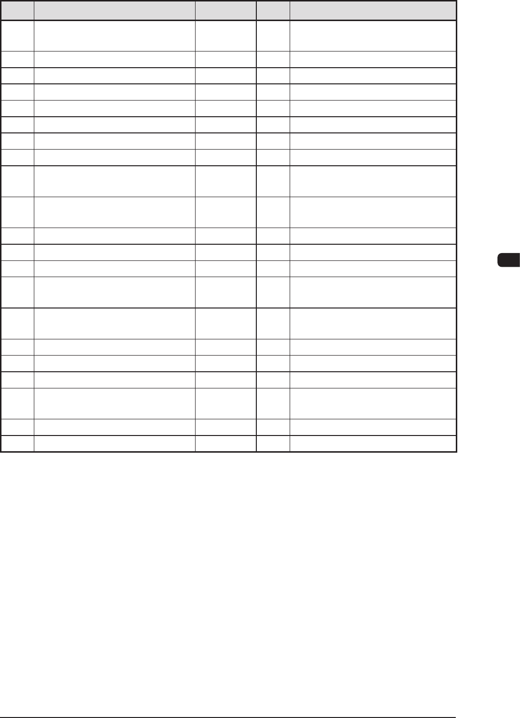
1.2 Standard Accessory Parts List
No. Product Name Part No. Q'ty Remarks
1 Lens Cleaning Cloth
15 cm
×
15 cm
226J1560 5
2 Glass Tube Fuse (6.3 A) 4S300023 1
•
Spare
3 Glass Tube Fuse (5 A) 4S300024 1
•
Spare
4 Glass Tube Fuse (3.15 A) 4V320011 1
•
Spare
5 Glass Tube Fuse (10 A) 4V320010 1
•
Spare
6 Fuse with an Alarm Contact (5A) 4S300006 1
•
Spare
7 Flat-Type Fuse (5 A) 4S300010 1
•
Spare
8 Fuse (2 A) 0916D207 1
•
Spare
9 Splicing Joint Detector Cleaning
Long Stick with a Rope
0926B109 1
•
For Cleaning the Splicing Joint
Detector
10 Splicing Joint Detector Cleaning
Cotton Applicator
0926B10A 1
•
For Cleaning the Splicing Joint
Detector
11 Flame Leg Receiver 216R0353 4
12 Collar (BS Spacer) 216A0334 4
•
Flame Leg Receiver
13 Set Screw 221CA010 4
•
Flame Leg Receiver
14 Padlock 226J0574 2
•
For Locking Power Breaker and
Air Source
15 QFP Glass Plate Jig
(JG-0188)
211D9639 1
•
For Of
fset Teaching
16 Nozzle (HA09) 09429104
1
17 Nozzle (PK01) 0974J00Q 1
•
For Support Pin Pick-up
18 Filter 225A0045 960
19 Flat Ring 226A0256 3
•
For Roller on Oscillating Side in
Cutter Section
20 Tape Cutting Jig 09141J03 1
21 PCB Support Pin 0974900M 40
•
For PCB Support Pin
T1E2-1
0911-001