1OM-1626-001_w.pdf - 第62页
1OM-1610 2. Name and Function of Each Section : Chap.1 1-5 091 1-001 Light Tower (2.6) Transparent Cover (2.4) Cover Lock Switch Rear Side of Machine [EMERGENCY STOP] Switch F1A3 Note The gures in brackets show the item…
1OM-1610
1-4
2. Name and Function of Each Section : Chap.1
0911-001
2. Name and Function of Each Section
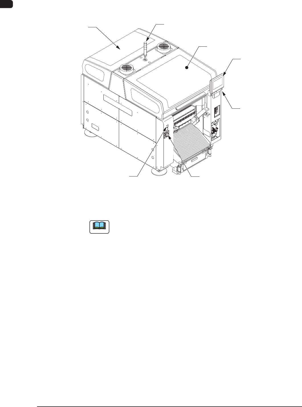
2.1 Appearance of Machine
Transparent
Cover (2.4)
Light Tower
(2.6)
Transparent Cover
(2.4)
Cover Lock Switch
(Stage Ready Switch)
Power Breaker
(2.5)
Front Side of Machine
Front Operation Panel
(2.7)
[EMERGENCY STOP]
Switch (2.2)
F1A2
Note
The gures in brackets show the item No.
1OM-1610
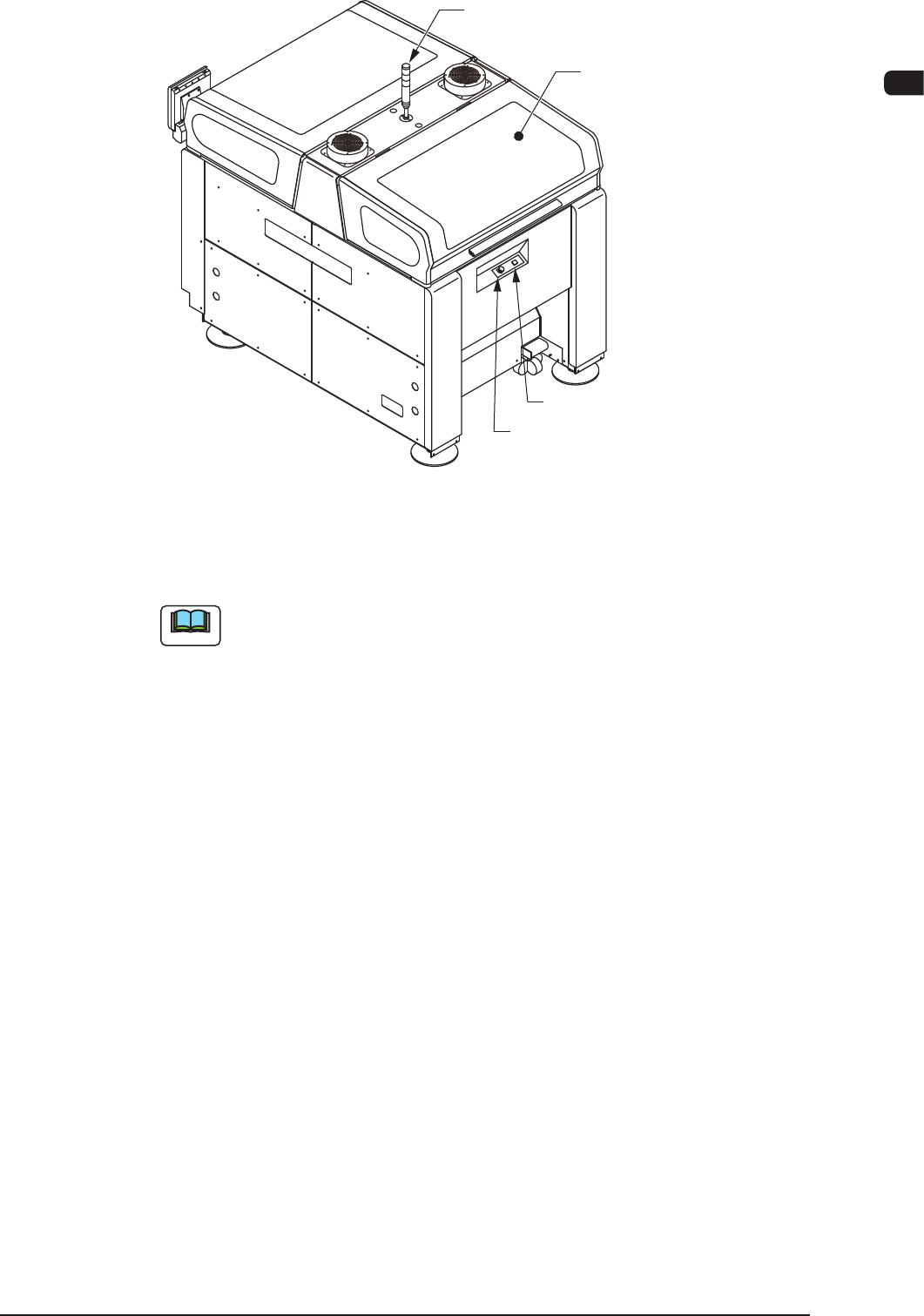
2. Name and Function of Each Section : Chap.1
1-50911-001
Light Tower
(2.6)
Transparent Cover
(2.4)
Cover Lock Switch
Rear Side of Machine
[EMERGENCY STOP] Switch
F1A3
Note
The gures in brackets show the item No.

1OM-1610
1-6
2. Name and Function of Each Section : Chap.1
0911-001
2.2 [EMERGENCY STOP] Switches
The [EMERGENCY STOP] switches can be used to stop the machine in an
emergency.
When one of the [EMERGENCY STOP] switches is pressed, the machine stops
immediately and the [POWER ON] button on the operation panel turns red.
[EMERGENCY STOP] Switches
F1A4
•
Locking the [EMERGENCY STOP] Switch
When one of the [EMERGENCY STOP] switches is pressed, the machine stops
and the switch is locked.
•
Unlocking the [EMERGENCY STOP] Switch
When one of the [EMERGENCY STOP] switch is pressed (locked), check and
remove the cause of the emergency stop. After that, recheck each section and
turn the switch clockwise to unlock.
Notice
The [EMERGENCY STOP] switches are used to intercept the controlled
power supply in an emergency.
Note
This machine is not provided with any emergency stop off function that can be
used to intercept the power supply to all loads in an emergency.
When "Emergency Switch Off" is required, it must be prepared outside the
machine on the customer side.