1OM-1626-001_w.pdf - 第191页
1OM-1610 5-10 1. Specications : Chap.5 091 1-001 Item Description 14. Number of Stocked Nozzles High-Speed Head Multi-Functional Head Nozzle Stocker for High-Speed Components Max. 15 nozzles can be stored for each head.…
1OM-1610
5-9
1. Specications : Chap.5
0911-001
Item Description
13. Placement Heads
High-Speed Head Multi-Functional Head
Equipped with 2 heads / 2 beams
Vacuum Nozzle: Max. 15 nozzles on
each head
Ref.
:
Maximum Number of
Component Picks:
Component Size
4 × 3 mm or less 15
to
7 × 7 mm or less 7
to
8 × 8 mm or less 5
to
10 × 10 mm or less 4
to 12 × 12 mm or less 3
to 20 × 20 mm or less 2
to
44 × 44 mm or less 1
Note
:
There are two types of
nozzles-one for high-speed
component placement and
the other for middle-size odd-
shaped component placement.
Although the nozzles for high-
speed and middle-size odd-
shaped components can be
used together, the nozzles
for middle-size odd-shaped
components must be attached,
leaving one out of every three
pitches empty due to the
location of the diffusion plates.
Nozzle for High-Speed
Component Placement :
The diameter is
φ
6 mm
or less. This nozzle
is used for 0402
components. Applicable
size of components :
0402 to 20
×
20 mm.
Nozzle for Middle-Size Odd-
Shaped Component Placement :
The diameter is
φ
12 mm
or less. The nozzle tip
is processed according
to the applicable
components.
The nozzle can be used
for the component size of
up to 44
×
44 mm.
Equipped with 2 heads / 2 beams
Vacuum Nozzle: Max. 3 nozzles on
each head
Ref.
:
Maximum Number of
Component Picks:
Component Size
26.2
× 26.2 mm or less 3
to 55 × 55
mm or less 2
Note
:
For components not within the
above ranges, the number of
components to be picked up
should be "1".
(In the case of connector 100
×
26 mm, etc.)
1OM-1610
5-10
1. Specications : Chap.5
0911-001
Item Description
14. Number of
Stocked Nozzles
High-Speed Head Multi-Functional Head
Nozzle Stocker for High-Speed
Components
Max. 15 nozzles can be stored for
each head.
Nozzle Stocker for Middle-Size
and Odd-Shape Components
Max. 8 nozzles can be stored for each
head.
Notes :
(a) Increase of the quantity
of nozzle to be stocked
is available by means
of adding the nozzle
stockers (option).
(b) When the vacuum
nozzles for the
middlesize and odd-
shape components are
used, the nozzle stockers
for the middle-size and
oddshape components
are required.
Nozzle Stocker for Multi-
Functional Head
Max. 9 nozzles can be stored for each
head.
Notes :
(a) Use the nozzle stocker
for multi-functional
head.
(b) Increase of the quantity
of nozzle to be stocked
is available by means
of adding the nozzle
stockers (option).
15. Number of
Installable
Feeders
(1) Tape Feeders
Max. 30 feeders
(when only 8 mm dual tape feeders are used)
Ref.
: Up to 120 types of components can be loaded.
Max. 30 feeders
(When only 12 / 16 mm tape feeders are used)
Max. 15 feeders
(When only 24 / 32 mm tape feeders are used)
Max. 10 feeders
(When only 44 / 56 mm tape feeders are used)
Max. 7 feeders
(When only 72 mm tape feeders are used)
(2) Vibratory Stick Feeders
Max. 5 per feeder base
Ref. :
Up to 6 carrier sticks can be installed on one vibratory stick feeder.
Notes :
(a)
The number of installable feeders varies according to the
combination of the reel width for the taping and the feeders.
(b) Use the tape feeder for the SIGMA- G4/G5. In the case that the
tape
feeder for the GXH-1 / GXH-3 series is used, the operational
conditions are partly restricted.
(c) The
dual tape feeder, bulk feeder and tapes for the other machines
(ie. machines excluding SIGMA-G4/G5, GXH-series) cannot be
used.
T1E1-10
1OM-1610
5-11
1. Specications : Chap.5
0911-001
Item Description
16. Memory Capacity
of Pattern
Program Data
Maximum Number of Steps : 20,000 steps/model (For repetitive patterns)
Maximum Memorized Number of Models : 24 models
Note :
The above numbers are limited according to the capacity of the
pattern program data per model.
17. Input System and
Output System of
Pattern Program
Data
•
Operated using the touch screen on the main machine and edited using the
keyboard/pointing device (Option).
•
Pattern program data can be edited with the network terminal (Option).
•
Data can be entered through the local area network (Ethernet) running from
the data storage device of the network terminal (Option).
•
Data
Transfer to Storage of Network Terminal (Option).
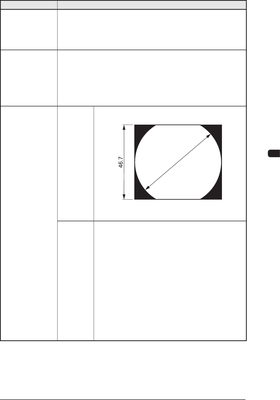
18. Component
Recognition
V
isual Field
φ
62 mm
The dimension in Y direction must be 46.7 mm.
Y (direction)
F 62
Unit : mm
Photoimage Front Lighting System
(Direct Recognition of Component by Front Lighting)
Note :
Some limitation is imposed, depending on the types of
components.
Back Lighting System
(Recognition by Component Silhouette)
Note :
Some limitation is imposed, depending on the types of
components.
In the back lighting system, specied nozzle are
required for the middle-size odd-shaped components
and the multifunctional nozzle on the multifunctional
head.
For the Back Lighting System, the static image is shot
using the camera.
T1E1-11