1OM-1626-001_w.pdf - 第202页
1OM-1610 5-21 1. Specications : Chap.5 1.3 Conditions for Component Placement (1) When components are to be placed close to the previously-placed components or the obstacles, the shape of the vacuum nozzle becomes part …
1OM-1610
5-20
1. Specications : Chap.5
1.2.1 Head Accessory List
• High Speed Head
No. Product Name Part No. Q'ty Remarks
1 Vacuum Filter 225B0572 90
2 High-Speed Nozzle Stocker
Replacement Section
09198000 1
T1E2-2
• Multi-Functional Head
No. Product Name Part No. Q'ty Remarks
1 Multi-Functional Head Filter 225B0313 18
T1E2-3
NOTE :
These head accessories are attached for each head.
0911-001
1OM-1610
5-21
1. Specications : Chap.5
1.3 Conditions for Component Placement
(1) When components are to be placed close to the previously-placed
components or the obstacles, the shape of the vacuum nozzle becomes part
of the constraint condition. Refer to "List of Nozzle Types" for the shapes of
vacuum nozzles.
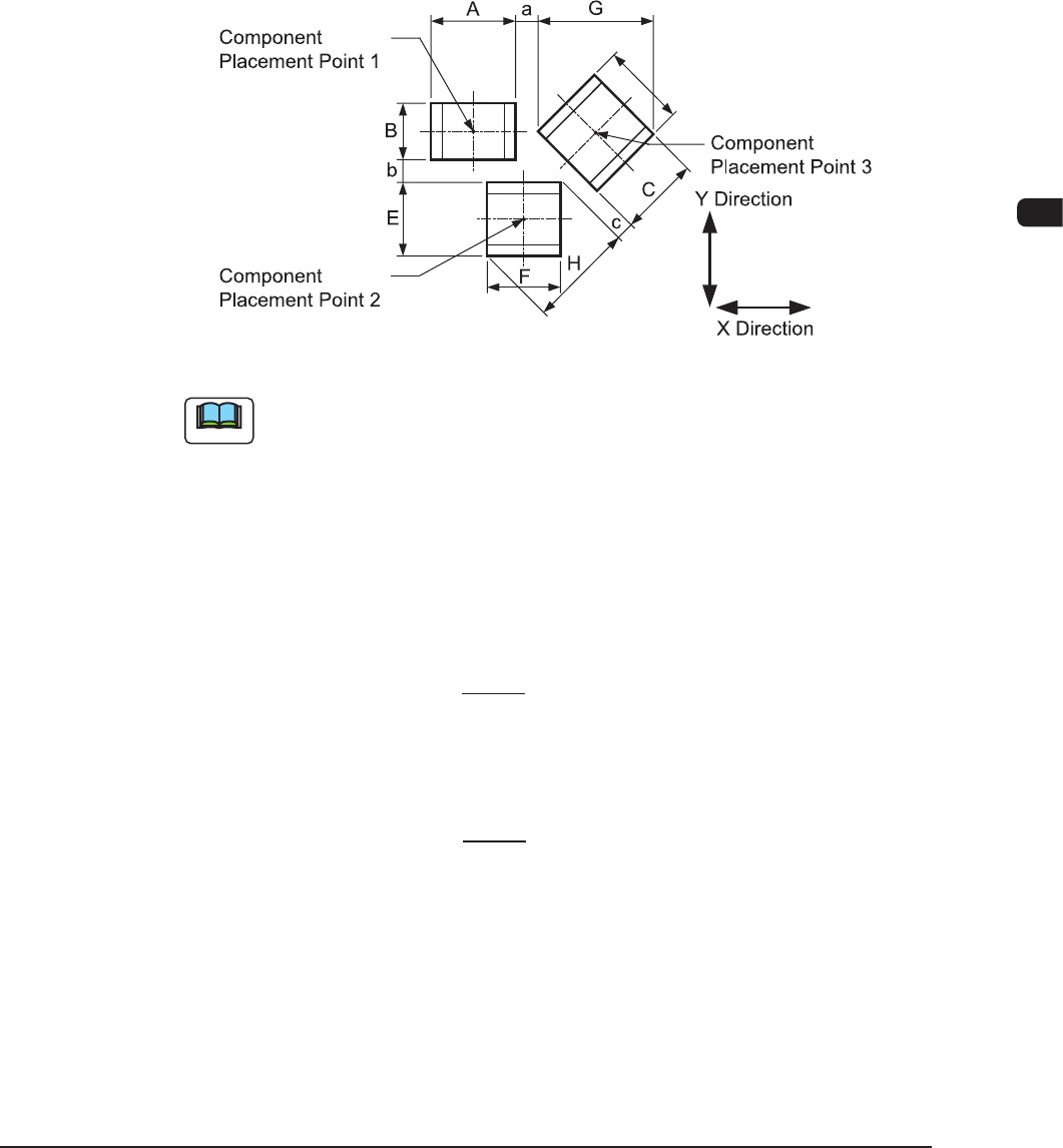
(2) Adjoining Distances between Components
(when the component placement position is taken into consideration)
F1E1
Note
(a) F1E1 shows that the vacuum nozzles are not protruding from the outer
shapes of components.
When components are placed, any placement deviation may be caused by
solder paste, glue, etc. Here, we don't take account of such deviation.
(b) A to H in the above gure show the maximum dimensions including the
variations in the dimensions of each component. The minimum adjoining
distances (a, b, and c) of each component should be 0.2 mm.
(c) The minimum adjoining placement position data for component placement
points 1 and 3 is
X Direction Data = + Min. 0.2 mm.
(The Y
direction data is not related.)
(d) The minimum adjoining placement position data for component placement
points 1 and 2 is
Y Direction Data = + Min. 0.2 mm.
(The X direction data is not related.)
(e)
See F1E1 and obtain the minimum adjoining placement position data for
component placement points 2 and 3.
A + G
2
B + E
2
0911-001
1OM-1610
5-22
1. Specications : Chap.5
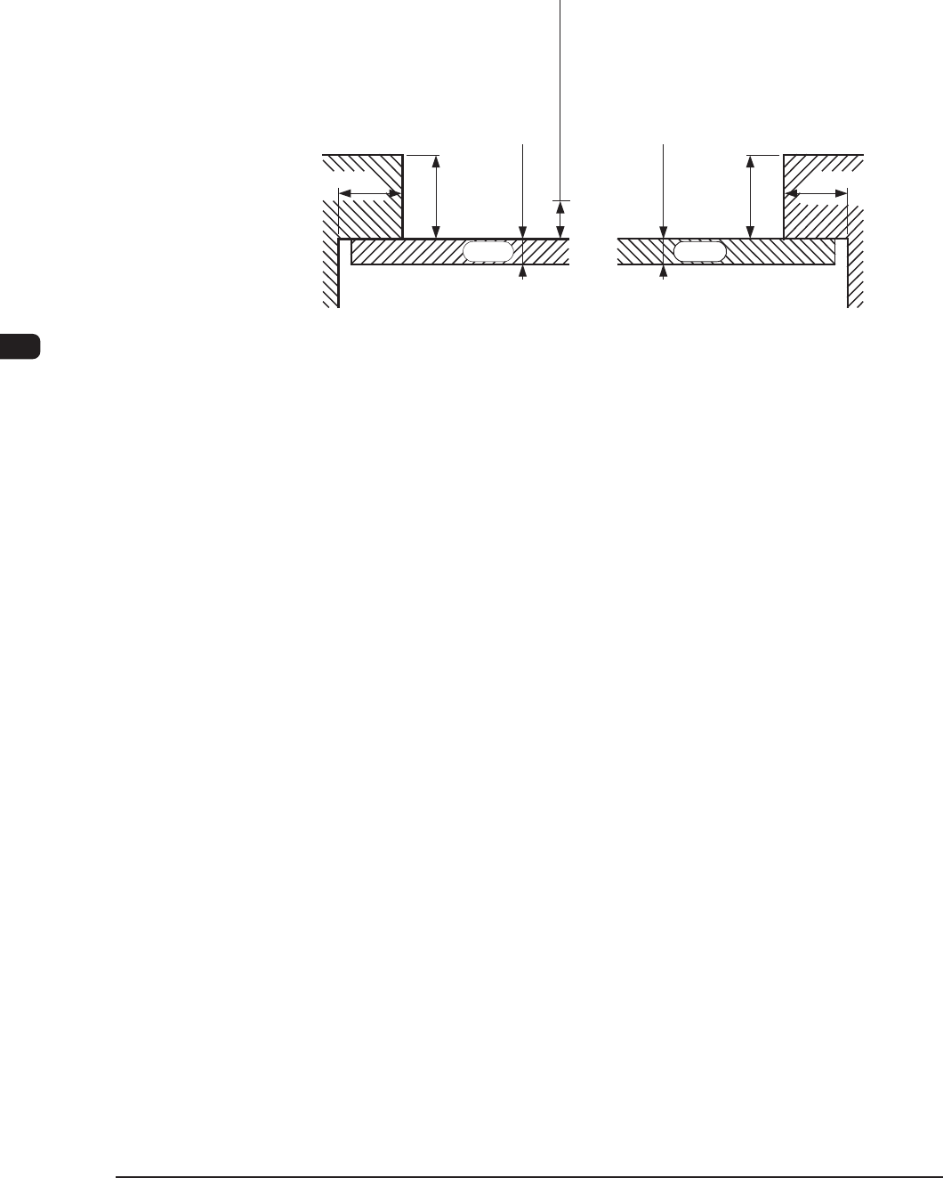
(3) Limit of Closest Distance to Obstacle
•
The closest distance between an obstacle (See each sectional view.) and
the vacuum nozzle or component should be 0.5 mm or more. The upper
surface of the PCB is the reference plane.
0.3 to 5.0
0.3 to 5.0
3.0
2.0
3.0
2.0
0.5 mm or more
PCB PCB
(Rear Side of Machine)(Front Side of Machine)
Limit of Closest Distance
Unit : mm
Section View of Chute F1E2
0911-001