1OM-1626-001_w.pdf - 第60页
1OM-1610 1. What is the direct drive modular mounter? : Chap.1 1-3 091 1-001 Recognition Unit • Non-Stop Fly Batch Recognition Components can be recognized collectively without stopping the heads that are moving at high…

1OM-1610
1-2
1. What is the direct drive modular mounter? : Chap.1
0911-001
1.2 Main Features
Beam Section
•
XY-Axis Linear Motor Driving
The X/Y axis driven by linear motors and scales realized highly accurate
component placement at high speed, reducing vibration and noise.
The Y-axis twin driving made it possible to achieve highly accurate
positioning at high speed.
•
2-Beam and 2-Head Structure
The machine has two stages and each stage is provided with front and rear
beams (2 heads and 2 beams in total).
The front and rear beams take component placement and pickup actions in
turn repeatedly, for efcient and continuous component placement.
Head Section
•
Multiheads
Each head is provided with line sensors which can measure component
height. The results of the measurement are fed back, realizing the best
amount of pushing distances for high quality component mounting.
Each head holds twelve nozzles that pick up components in succession,
reducing the shuttling frequency of the beams for realization of high
throughput.
A simulation is made to determine the number of components to be placed
at a time, enabling the best selection in the number of nozzles for the
multiheads.
•
Component Thickness Measurement
The picked component thickness is measured using a line sensor and the
acquired data is fed back to the height for component placement.
The vacuum nozzle detection function enables detection of an overcarried
component, realizes highly accurate detection, and ensures high quality
placement.
•
Soft Mounting Nozzle
This nozzle can be used for soft component placement because it reduces
impacts caused due to upward wapage of PCBs which affects minute
components of 1005 size or less.
Minute component placement without two-step speed reduction becomes
possible for improved productivity.

1OM-1610
1. What is the direct drive modular mounter? : Chap.1
1-30911-001
Recognition Unit
•
Non-Stop Fly Batch Recognition
Components can be recognized collectively without stopping the heads
that are moving at high speed. This function is called "Non-Stop Fly Batch
Recognition".
Images without any distortion can be captured though the telecentric lens,
realizing the multiple recognition. This highly accurate multiple recognition
function is used to recognize up to 15 components collectively at high speed.
Cart Installation
•
Intelligent Motor-Driven Feeders
The adoption of motors for tape feeding realized highly accurate component
supply at high speed without any hindrance even for minute fragile (weak to
shocks) components.
The machine is provided with bank feeder change carts that can be loaded
with various types of components (more than the conventional types),
reducing the time for feeder setup operations.
The tape splicing function also enabled the continuous production (non-stop
operation of the machine).
PCB Transfer Section
•
Dual
Transfer
The dual transfer function that uses two PCB feeding lanes, transfers two
PCBs from the input machine alternatively in these two lanes to enhance the
productivity.
•
PCB Height Measurement Feedback Function (Optional)
Before the machine places components on a PCB, the thickness of the PCB
upper surface is measured using a laser and is fed back to the height for
component placement.
It is possible to signicantly suppress stress imposed on components during
placement due to upward warpage of PCBs and reduce solder bridges for
high quality component placement.
1OM-1610
1-4
2. Name and Function of Each Section : Chap.1
0911-001
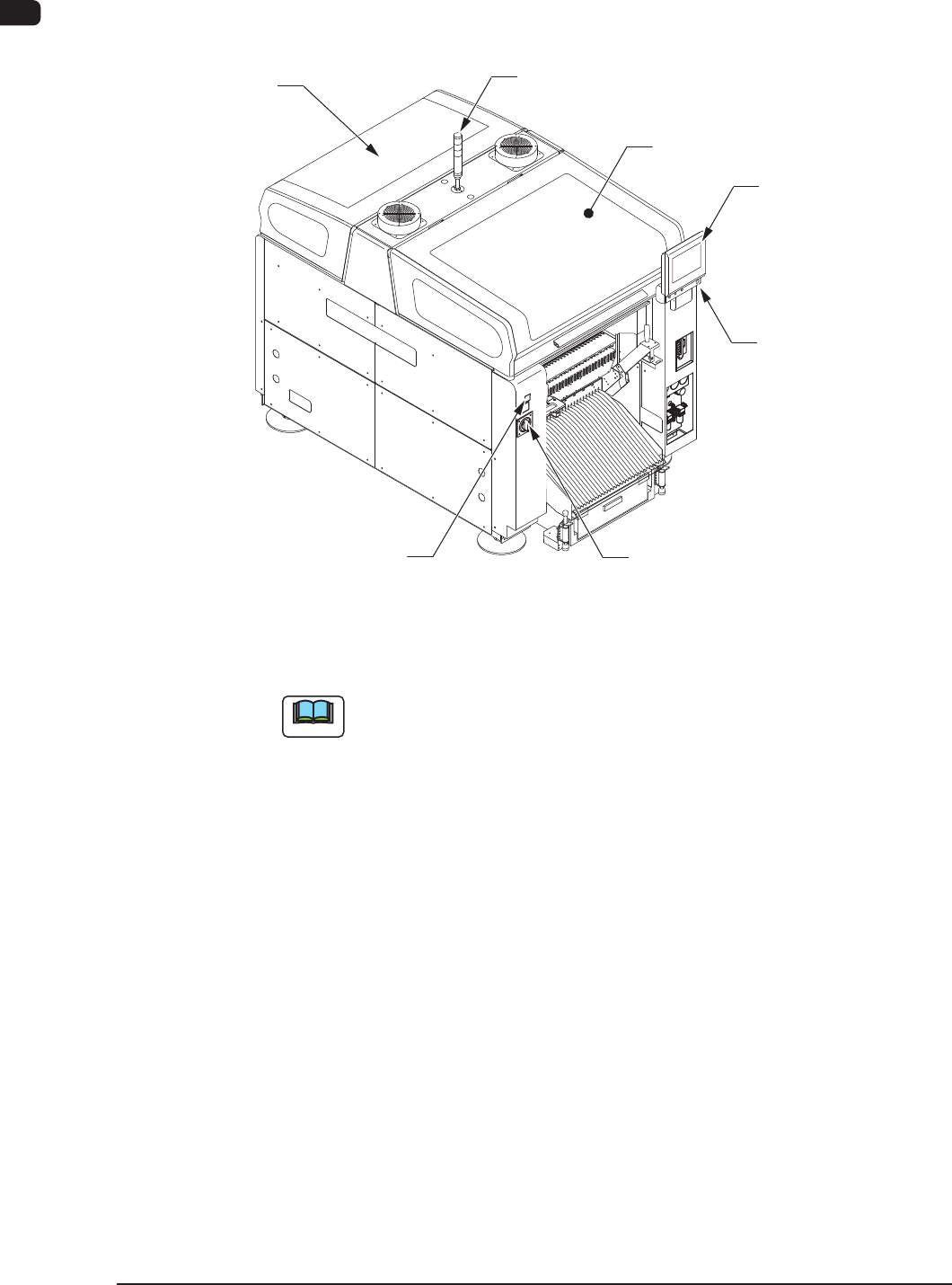
2. Name and Function of Each Section
2.1 Appearance of Machine
Transparent
Cover (2.4)
Light Tower
(2.6)
Transparent Cover
(2.4)
Cover Lock Switch
(Stage Ready Switch)
Power Breaker
(2.5)
Front Side of Machine
Front Operation Panel
(2.7)
[EMERGENCY STOP]
Switch (2.2)
F1A2
Note
The gures in brackets show the item No.