1OM-1626-001_w.pdf - 第75页
1OM-1610 1-18 3. Mechanism for Surface Mounting : Chap.1 091 1-001 3. Mechanism for Surface Mounting 3.1 Location of Related Units The following units are used for the surface mounting. Nozzle Stocker Section Component R…
1OM-1610
2. Name and Function of Each Section : Chap.1
1-170911-001
(1) Notes on Handling Touch Screen
•
Since the touch screen uses the molecules in liquid crystals, handle it like
glass. Do not apply any strong pressure or shock to the surface.
Notice
Do not apply any strong pressure or shock to the touch screens.
Otherwise, they will be damaged.
Do not press the touch screens with a force of 0.79N (80 g) or
more.
•
When the machine is powered under low temperature, the brightness of
the back light drops. It turns out to be normal in a few minutes and the
deterioration is not abnormal.
When the back light is turned on or off repeatedly at low temperature, the
life will be shortened.
•
Before cleaning the touch screen, be sure to turn off the [POWER ON]
button. Otherwise, the touch screen will react to your touch during cleaning,
resulting in data corruption.
If the surface of the touch screen gets dirty, wipe it softly with a soft cloth
soaked in ethanol to remove dirt and dust.
Notice
Never use an organic solvent such as acetone, thinner, benzine to
clean the touch screens.
If the surface is wiped with an organic solvent, it may melt or get
cloudy.
Short Appendix : Operation Panels and Touch Screens
1OM-1610
1-18
3. Mechanism for Surface Mounting : Chap.1
0911-001
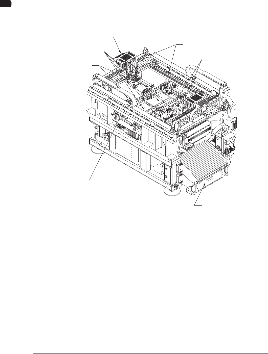
3. Mechanism for Surface Mounting
3.1 Location of Related Units
The following units are used for the surface mounting.
Nozzle Stocker Section
Component Recognition
Section
Cart Installation Section
PCB Transfer Section
Placement Head Section,
PEC Recognition Section
PCB Positioning Section
XY Beam Section
F1A14
1OM-1610
3. Mechanism for Surface Mounting : Chap.1
1-190911-001
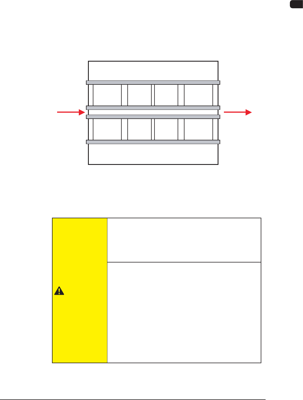
3.2 PCB Transfer Section (PCB Input and Output Sections)
The PCB transfer mechanism works to transfer the PCB (sent from the input
machine) to the area just before the PCB positioning section and carries out the
component-placed PCB to the output machine.
The PCB sent from the input machine is transferred to the area just before the
PCB positioning section by the PCB input section.
The componentplaced PCB transferred from the PCB positioning section on the
output side is carried further to the output machine by the PCB output section.
Input
Machine
Buffer Section
Locating "L"
Section
Locating "R"
Section
Buffer Section
Output
Machine
F1A15
The PCB input section and PCB output section also serve as buffers.
Also, these sections are used as connecting sections to the external machines or to
the PCB positioning section.
CAUTION
Before operating the machine, conrm that there are no
people around the machine (especially, the other side of
the machine operation) and no objects such as tools and
parts are left around the machine.
When a PCB is trapped in the PCB receiving area
between the main machine and the input or the
output machine, be sure to stop the machine before
removing the PCB.
Depending on the setting of the PCB discharge from the
input machine to the output machine, the conveyor might
be moved in direction Y because the "PCB Direction Y
Arrangement Operation" is performed at the moment
when the PCB is removed. In such case, your nger might
be caught.