1OM-1626-001_w.pdf - 第201页
1OM-1610 5-20 1. Specications : Chap.5 1.2.1 Head Accessory List • High Speed Head No. Product Name Part No. Q'ty Remarks 1 V acuum Filter 225B0572 90 2 High-Speed Nozzle Stocker Replacement Section 09198000 1 T1E2…

1OM-1610
5-19
1. Specications : Chap.5
1.2 Standard Accessory Parts List
No. Product Name Part No. Q'ty Remarks
1 Lens Cleaning Cloth
15 cm
×
15 cm
226J1560 5
2 Glass Tube Fuse (6.3 A) 4S300023 1
•
Spare
3 Glass Tube Fuse (5 A) 4S300024 1
•
Spare
4 Glass Tube Fuse (3.15 A) 4V320011 1
•
Spare
5 Glass Tube Fuse (10 A) 4V320010 1
•
Spare
6 Fuse with an Alarm Contact (5A) 4S300006 1
•
Spare
7 Flat-Type Fuse (5 A) 4S300010 1
•
Spare
8 Fuse (2 A) 0916D207 1
•
Spare
9 Splicing Joint Detector Cleaning
Long Stick with a Rope
0926B109 1
•
For Cleaning the Splicing Joint
Detector
10 Splicing Joint Detector Cleaning
Cotton Applicator
0926B10A 1
•
For Cleaning the Splicing Joint
Detector
11 Flame Leg Receiver 216R0353 4
12 Collar (BS Spacer) 216A0334 4
•
Flame Leg Receiver
13 Set Screw 221CA010 4
•
Flame Leg Receiver
14 Padlock 226J0574 2
•
For Locking Power Breaker and
Air Source
15 QFP Glass Plate Jig
(JG-0188)
211D9639 1
•
For Of
fset Teaching
16 Nozzle (HA09) 09429104
1
17 Nozzle (PK01) 0974J00Q 1
•
For Support Pin Pick-up
18 Filter 225A0045 960
19 Flat Ring 226A0256 3
•
For Roller on Oscillating Side in
Cutter Section
20 Tape Cutting Jig 09141J03 1
21 PCB Support Pin 0974900M 40
•
For PCB Support Pin
T1E2-1
0911-001

1OM-1610
5-20
1. Specications : Chap.5
1.2.1 Head Accessory List
• High Speed Head
No. Product Name Part No. Q'ty Remarks
1 Vacuum Filter 225B0572 90
2 High-Speed Nozzle Stocker
Replacement Section
09198000 1
T1E2-2
• Multi-Functional Head
No. Product Name Part No. Q'ty Remarks
1 Multi-Functional Head Filter 225B0313 18
T1E2-3
NOTE :
These head accessories are attached for each head.
0911-001
1OM-1610
5-21
1. Specications : Chap.5
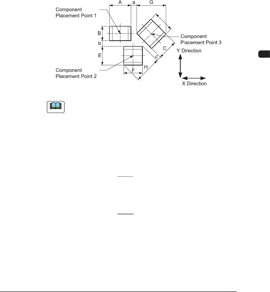
1.3 Conditions for Component Placement
(1) When components are to be placed close to the previously-placed
components or the obstacles, the shape of the vacuum nozzle becomes part
of the constraint condition. Refer to "List of Nozzle Types" for the shapes of
vacuum nozzles.
(2) Adjoining Distances between Components
(when the component placement position is taken into consideration)
F1E1
Note
(a) F1E1 shows that the vacuum nozzles are not protruding from the outer
shapes of components.
When components are placed, any placement deviation may be caused by
solder paste, glue, etc. Here, we don't take account of such deviation.
(b) A to H in the above gure show the maximum dimensions including the
variations in the dimensions of each component. The minimum adjoining
distances (a, b, and c) of each component should be 0.2 mm.
(c) The minimum adjoining placement position data for component placement
points 1 and 3 is
X Direction Data = + Min. 0.2 mm.
(The Y
direction data is not related.)
(d) The minimum adjoining placement position data for component placement
points 1 and 2 is
Y Direction Data = + Min. 0.2 mm.
(The X direction data is not related.)
(e)
See F1E1 and obtain the minimum adjoining placement position data for
component placement points 2 and 3.
A + G
2
B + E
2
0911-001