1OM-1626-001_w.pdf - 第71页
1OM-1610 1-14 2. Name and Function of Each Section : Chap.1 091 1-001 2.6 Light Tower The light tower indicates the condition of the machine with the lamps and buzzer sounds. Red Y ellow Green Buzzer Light T ower F1A11 •…
1OM-1610
2. Name and Function of Each Section : Chap.1
1-130911-001
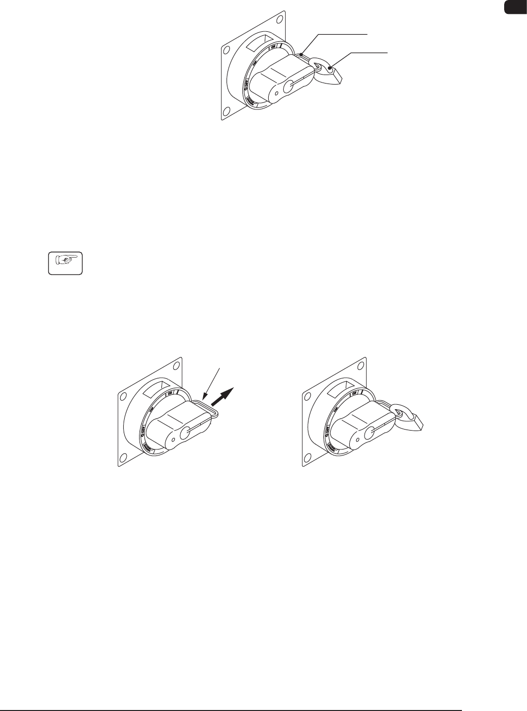
2.5.2 Unlocking the Power Breaker
Remove the padlock from the lock lever of the power breaker.
Front Side of Machine
Power Breaker
Lock Lever
Padlock
Locking the Power Breaker
F1A9
2.5.3 Locking the Power Breaker
Lock the power breaker with the padlock when the machine is not to be used for a
long period of time.
Procedure
(1) Pull out the lock lever of the power breaker in Direction A (indicated in the
gure below).
(Be sure not to release your hand from the lock lever. Otherwise, the lock
lever will pull back in place.)
(2) Engage the shackle of the padlock through the lock slot and lock the crank.
A
(Unlocked) (Locked)
Lock Lever
F1A10
1OM-1610
1-14
2. Name and Function of Each Section : Chap.1
0911-001
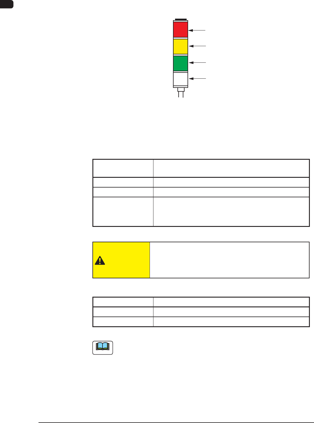
2.6 Light Tower
The light tower indicates the condition of the machine with the lamps and buzzer
sounds.
Red
Yellow
Green
Buzzer
Light Tower
F1A11
•
Lamp Colors (ON Mode)
The machine is factory-adjusted upon shipment.
Lamp Colors
(ON Mode)
Machine Condition
Red
Error (Operation Stopped)
Yellow
Component Shortage (Warning)
Green
Automatic Operation
When the machine is in the standby mode, this lamp
ickers.
T1A3
CAUTION
When the green lamp of the light tower is ON or
ickering(ONandOFF),itindicatesthatthestatic
machine is in the "Automatic" mode (standby mode).
•
Buzzer
Buzzer Machine Condition
Continuous Sound
Emergency Stop
Intermittent Sound
Error
T1A4
Note
The condition of the machine corresponding to the parameters specied for each
lamp color and buzzer sound can be changed in the "Machine Setup" window.
1OM-1610
2. Name and Function of Each Section : Chap.1
1-150911-001
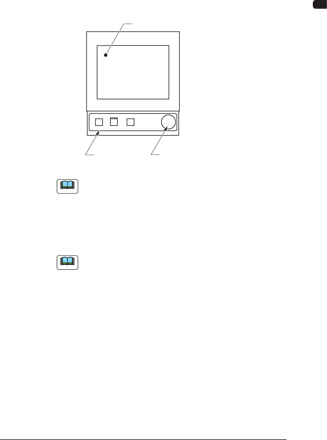
2.7 Operation Section
The machine is equipped with touch screens and operation panels for machine
operations.
[EMERGENCY STOP] SwitchesOperation Panels
Touch Screens
F1A12
Note
The keyboard and track ball are not attached, but they can be attached as
options.
2.7.1 Touch Screens
The windows for operations are displayed on the touch screens.
Various operations can be performed by nger-touching the buttons that appear
on the screen.
Note
Refer to "Short Appendix : Operation Panels and Touch Screens" for how to
handle the touch screens.