1OM-1626-001_w.pdf - 第167页
1OM-1610 4-10 3. Program Change Operation : Chap.4 091 1-001 (6) Conrm that a PCB support pin, etc., is not left behind on the backup table. Conrm that no component or dust, etc., has fallen into the holes on the backu…
1OM-1610
4-9
3. Program Change Operation : Chap.4
0911-001
3.3.2 Attachment of PCB Support Pins
The PCB support pins are used to keep the upper surface of the PCB in proper
height for stabilization of the component placement.If the conveyor width is not
correctly set, the PCB support pins cannot be attached correctly.
Note
When 0603 components must be placed, it is important to secure the atness of
the PCB.Use the support pins or a backup plate.
Consult the marketing department or sales agency of Hitachi High-Technologies
for how to make a backup plate.
Procedure
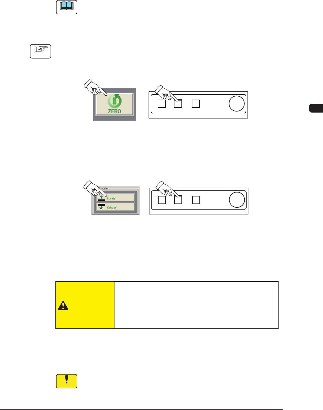
(1) Press the [ZERO] button in the "Control" window.
In 10 seconds, press the [START] button on the operation panel. The
machine starts a zeroing operation.
F1D8
(2) Press the [Locate] button in the "PCB Locate" group box.
In 10 seconds, press the [START] button on the operation panel. The backup
base moves up.
F1D9
(3) Press the pertinent cover lock switch. The lamp of the switch extinguishes.
The transparent cover (door type) is unlocked.
(4) Open the transparent cover (door type).
CAUTION
The load power to the motors, etc., is turned OFF
but the setup operation must be performed carefully
when you put your hand inside the machine.
(5) Insert the PCB support pins vertically in the holes in the stock area on the
backup table.
(Edit the parameters for the stock area setting when necessary).
Notice
Do not put your hand or any heavy object on the backup table while
working with the backup table. Otherwise, the backup table may become
deformed due to an excessive load.
1OM-1610
4-10
3. Program Change Operation : Chap.4
0911-001
(6) Conrm that a PCB support pin, etc., is not left behind on the backup table.
Conrm that no component or dust, etc., has fallen into the holes on the
backup table.
(7) Close the transparent cover (door type).
(8) Press the cover lock switch. The lamp of the switch illuminates. The
transparent cover (door type) is locked.
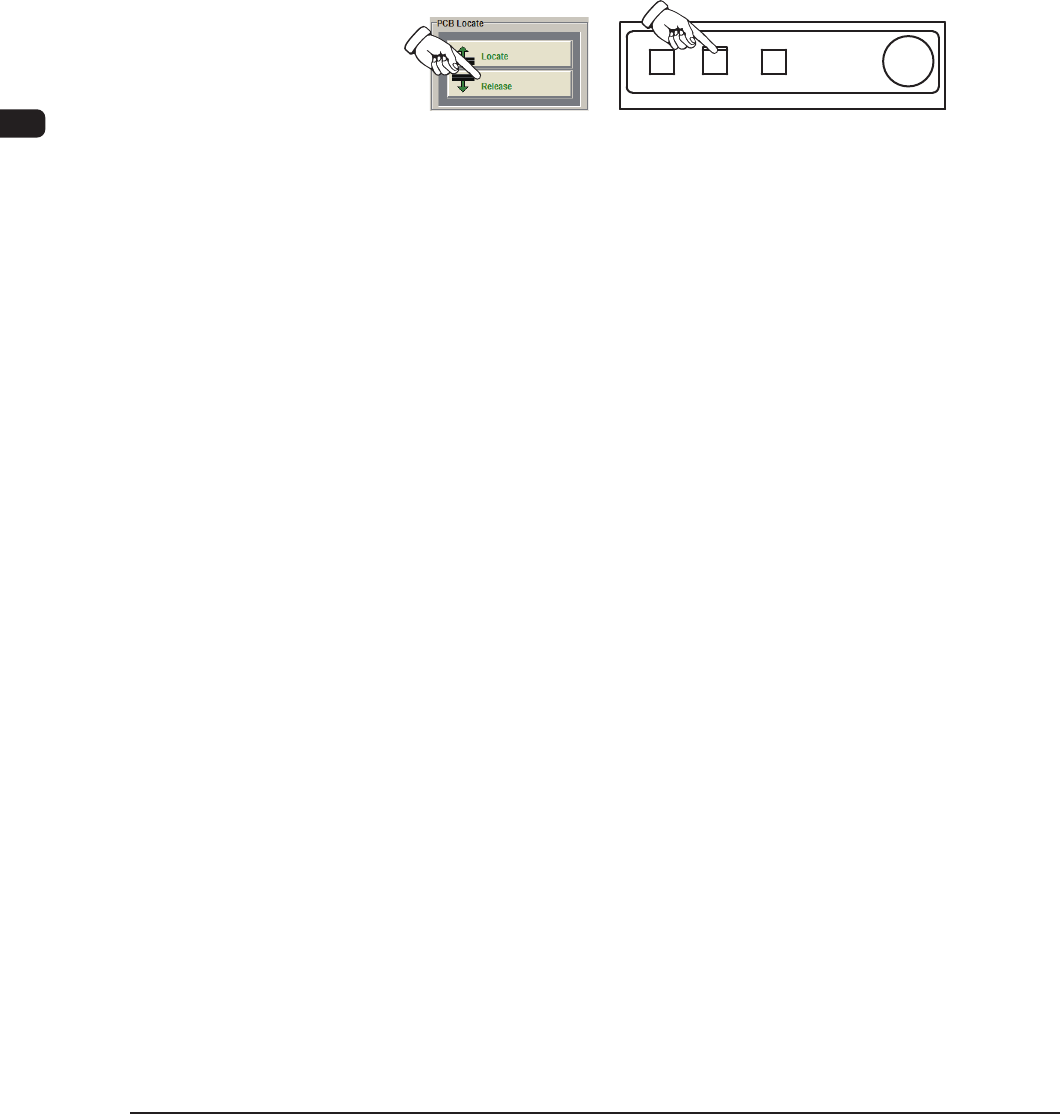
(9) Press the [Release] button in the "PCB Locate" group box.
In 10 seconds, press the [START] button on the operation panel. The backup
table moves down.
F1D10
1OM-1610
4-11
3. Program Change Operation : Chap.4
0911-001
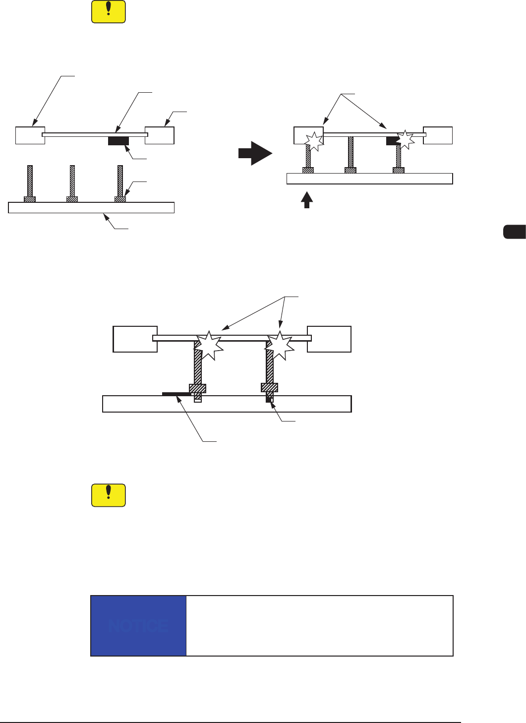
3.3.3 Notes on Attachment / Detachment of PCB Support Pins
Notice
Be sure to insert the PCB support pins at right angles.
•
When a PCB support pin is inserted at the bottom side of the chute, it
may collide
with the backup table while the backup table is moving up.
•
If the pins are inserted improperly, the machine will break down.
Chute
PCB
Previously-Placed
Component
Chute
PCB Support Pin
Backup Table
Collision!
Backup Table Up Movement
Improper Pin Insertion
F1D12
Collision!
Foreign Substance on Backup Table
Foreign Substance such
as a component trapped in the hole
F1D13
Notice
(a) When a component is trapped or dust has accumulated on the
backup table, the PCB support pins cannot be set correctly.
In this case, remove the component or the dust with a vacuum
cleaner, etc. (Air Blowing Prohibited).
(b) Do not put your hand or any heavy object on the backup table while
working with the backup table. Otherwise, the backup table may
become deformed due to an excessive load.
NOTICE
When some components are previously placed on the back
of the PCB, the PCB support pins must be inserted such
that they do not touch any component.