MAN00000772_SI-G200BB_SVCPDFA.pdf - 第156页
HLGB-10101-01 Insta ll the Calibration Plate Jig Click the Abs. Move button on the Conv . Adj. screen. Input “186” into th e inp ut box of the Conv . Width Abs. Pos. Press the [ST ART ] butt on on the operation pane l . …
HLGB-10101-01
Install the Calibration Plate Jig
Operations to use the calibration plate jig are as follows.
When performing the following operations, install the calibration plate jig according to the procedure
described in this section.
Set-Up
Calibration
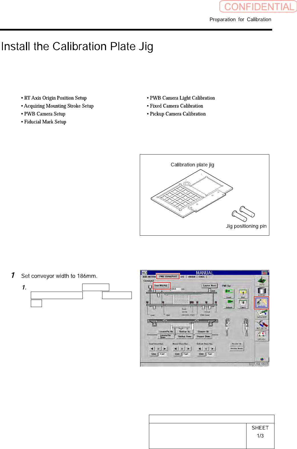
[Necessary jigs]
•
Calibrationplatejig
• Jig positioning pin
[Procedure]
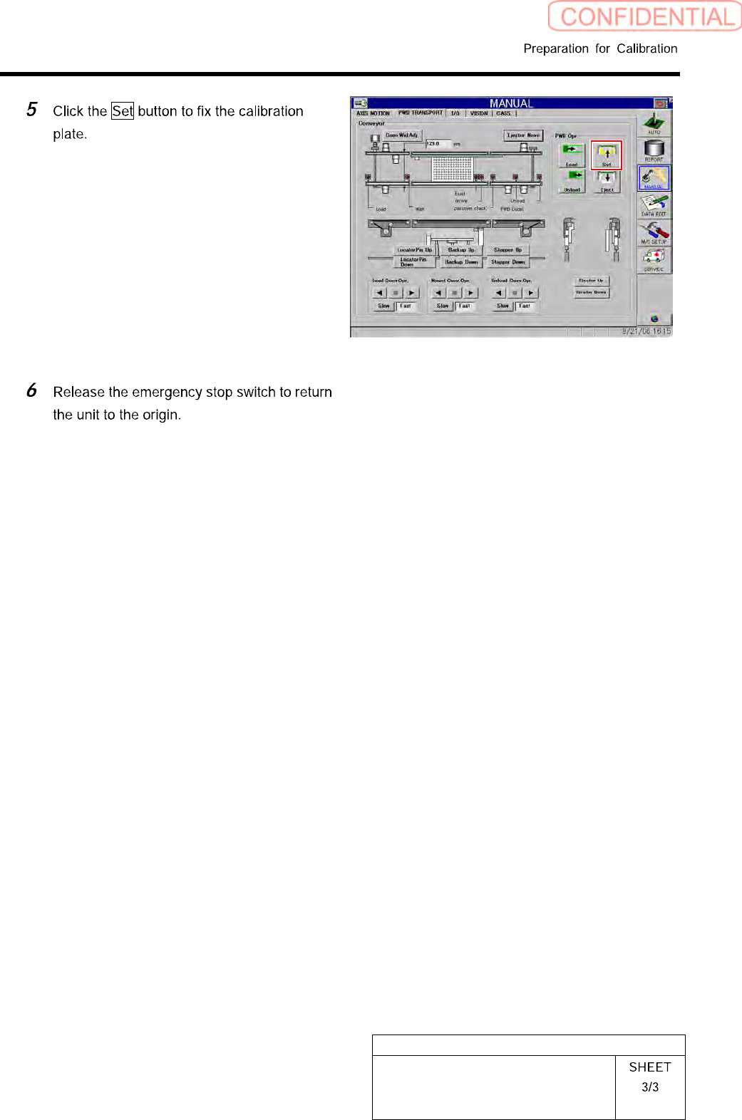
Click in an order of MANUAL menu
PWB TRANSPORT tab Conv. Wid.
Adj. button.
HLGB-10101-01
Install the Calibration Plate Jig
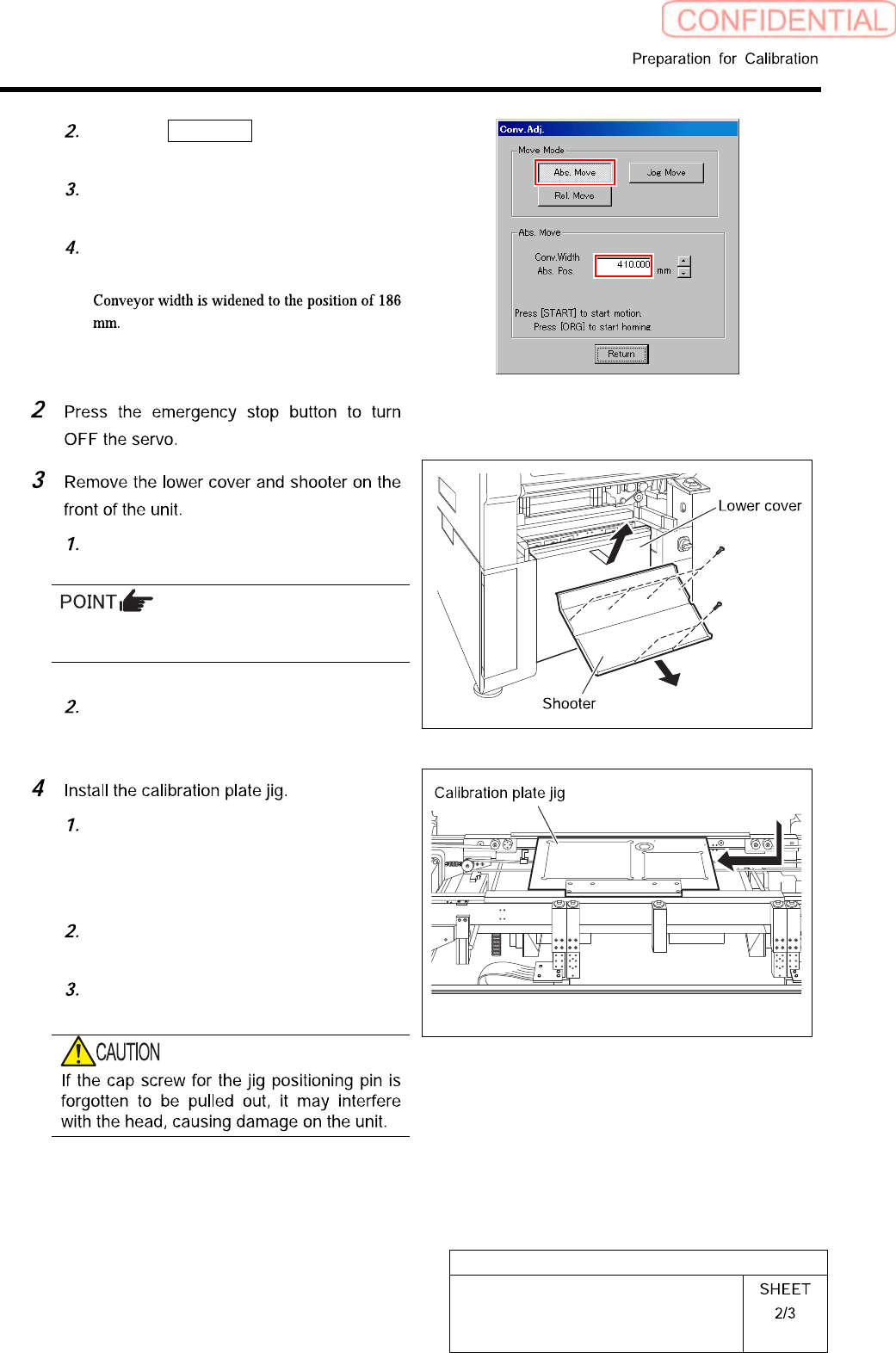
Click the Abs. Move button on the
Conv. Adj. screen.
Input “186” into the input box of the
Conv. Width Abs. Pos.
Press the [START] button on the
operation panel.
Loosen screw (2-+T4x8) to remove the
lower cover.
Tile the lower cover slightly toward you and
pull the fan cable to remove the lower panel.
Loosen screw (2-+T4x8) to remove the
shooter.
Place the calibration plate jig on the
rail on the right of the conveyor and
slide it to near the center of the
conveyor.
Insert the jig positioning pins (two)
into the calibration plate jig.
Remove the cap screw for jig
positioning pin.
HLGB-10101-01
Install the Calibration Plate Jig