MAN00000772_SI-G200BB_SVCPDFA.pdf - 第242页
HLGB-10310-01 Fixed Camera Rcg Height Calibration Press the [ST ART] butto n on the operation panel. Install the length reference noz z le jig to the turret No.1. When installing the nozzle, insert it while slowly turnin…
HLGB-10310-01
Fixed Camera Rcg Height Calibration
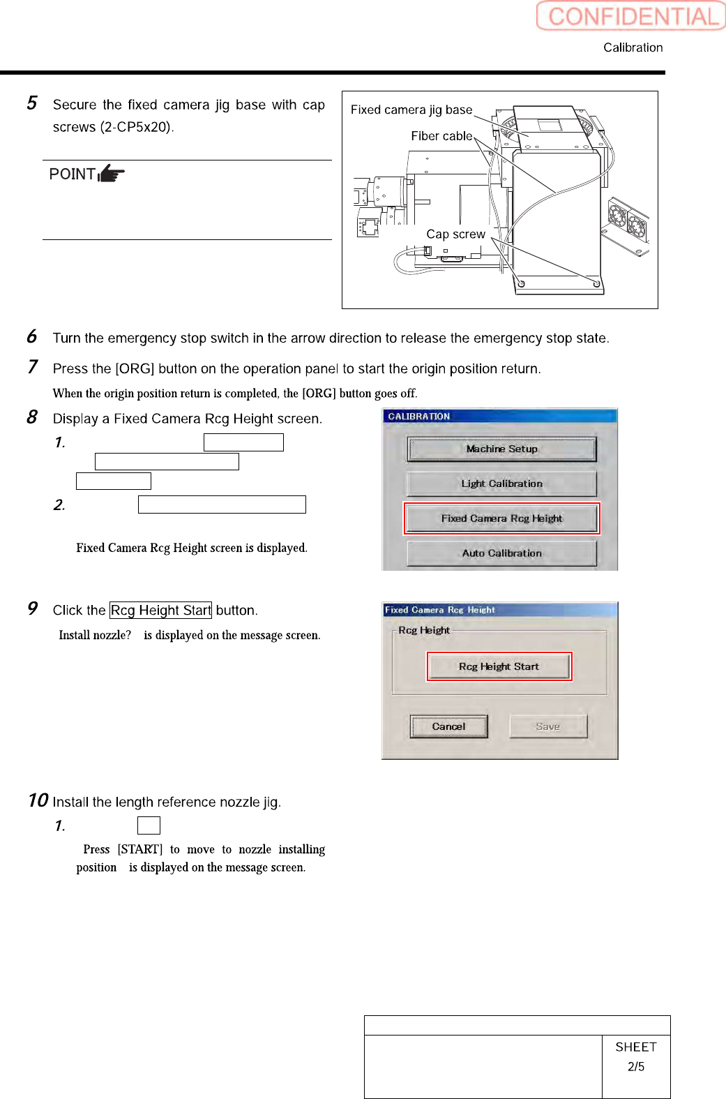
Carry out working with care not to damage the
fiber cable for parts presence/absence detecting
sensor.
Click in an order of M/C SETUP menu
M/C MAINTENANCE tab
Calibration button.
Click the Fixed Camera Rcg Height
button on the CALIBRATION screen.
“ ”
Click the Yes button.
“
”
HLGB-10310-01
Fixed Camera Rcg Height Calibration
Press the [START] button on the
operation panel.
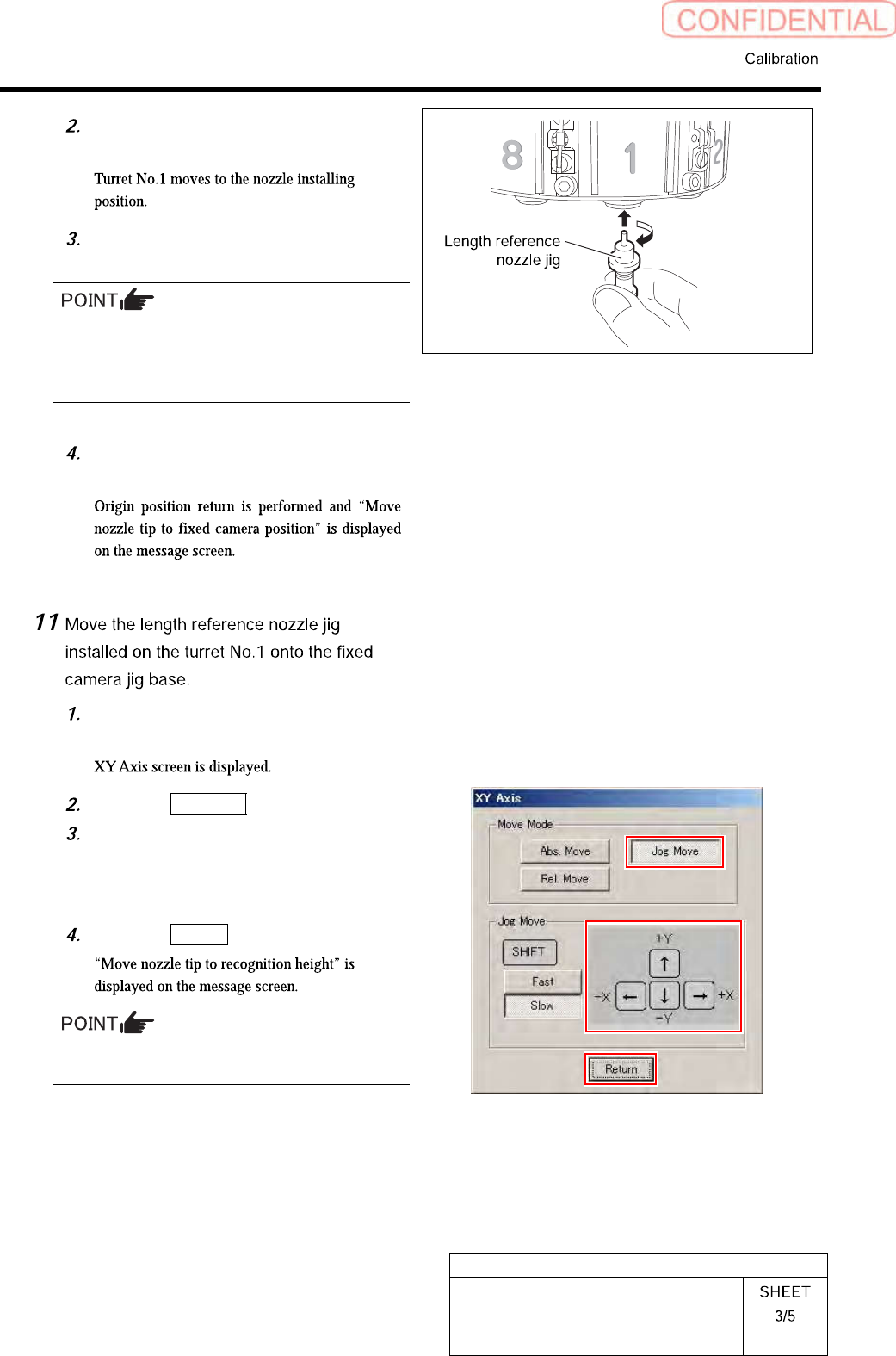
Install the length reference nozzle jig
to the turret No.1.
When installing the nozzle, insert it while
slowly turning.
After inserting the nozzle, check that it is not
drawn out by pulling downward.
Press the [ORG] button on the
operation panel.
Press the [START] button on the
operation panel.
Click the Jog Move button.
Press the cursor keys to jog move the
length reference nozzle jig onto the
fixed camera jig base (high level
difference face).
Click the Return button.
If the Shift key on the keyboard is pressed,
Fast/Slow for Jog Move can be switched.
HLGB-10310-01
Fixed Camera Rcg Height Calibration
Press the [START] button on the
operation panel.
Click the Jog Move button.
Press the downward cursor key to
lower the length reference nozzle jig to
height of 0.03mm above the fixed
camera jig base (high level difference
face).
If any error occurs when lowering the length
reference nozzle jig, change the negative values
of the H axis software limit to remedy as
follows.
Click in an order of the M/C SETUP menu
MOTOR PARAMETER tab Axis param. tab
and change the negative value of H axis
software limit from [-15.0] to [-16.0].
After fixed camera rcg height is completed, be
sure to return the value of software limit to the
original value.
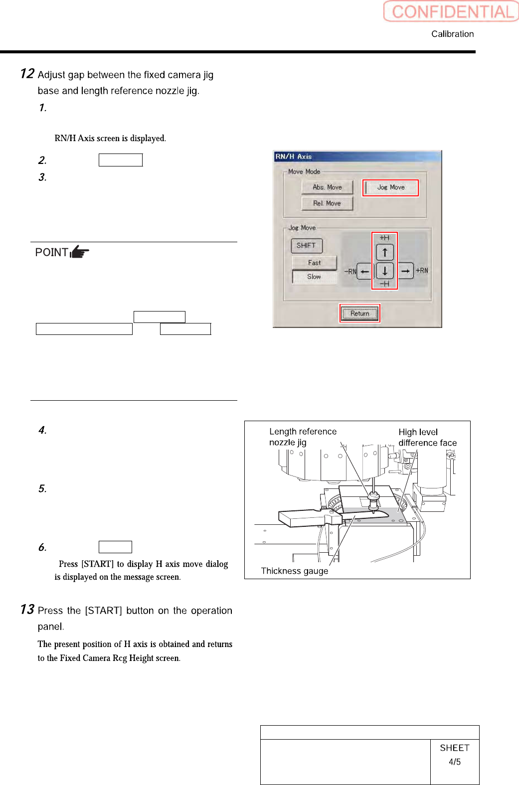
Check the gap between the length
reference nozzle jig and fixed camera
jig base (high level difference face)
using thickness gauge of 0.03mm.
After adjusting the gap, pull out the
thickness gauge and lower the H axis
by 0.03 mm (three click) by Low speed
Jog Move.
Click the Return button.
“ ”