MAN00000772_SI-G200BB_SVCPDFA.pdf - 第180页
HLGB-10203-01 Acquiring Mounting Stro ke Setu p Input a value of 1/1000 of the valu e described in calib.ini into the Mount height. Example: Press the Set button.
HLGB-10203-01
Acquiring Mounting Stroke Setup
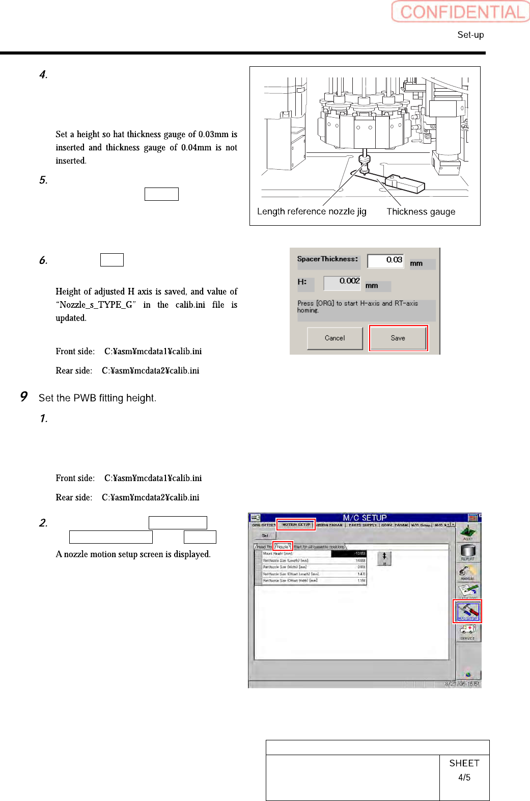
Check the gap between the length
reference nozzle jig and calibration
plate jig using thickness gauge of
0.03mm.
After completing to adjust the gap of
0.03mm, press the Return button on
the RN/H Axis screen to return to the
Acquiring mounting stroke screen.
Click the Save button on the Acquiring
mounting stroke screen.
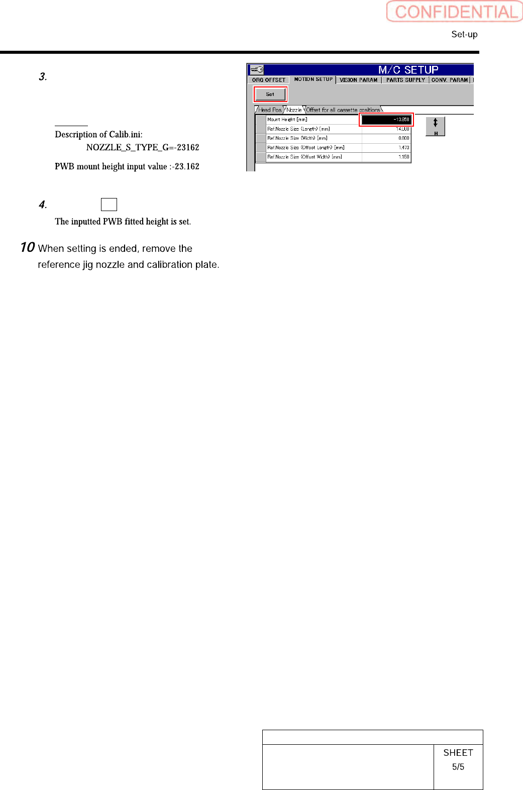
< Storing area of calib.ini file >
Record the value of
NOZZLE_S_TYPE_G described in
calib.ini.
< Storing area of calib.ini file >
Click in an order of M/C SETUP menu
MOTION SETUP tab Nozzle tab.
HLGB-10203-01
Acquiring Mounting Stroke Setup
Input a value of 1/1000 of the value
described in calib.ini into the Mount
height.
Example:
Press the Set button.
HLGB-10204-01
PWB Camera Setup
Perform this working on both heads on the front side and rear side.
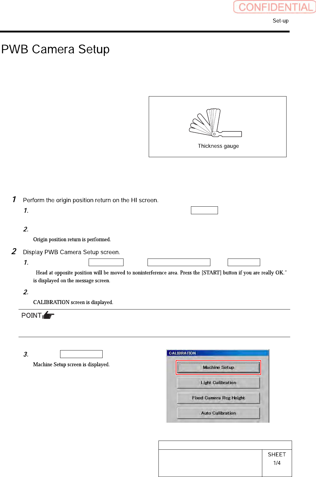
[Necessary jigs]
• Thickness gauge (t=1.0 mm)
[Procedure]
When the CALIBRATION screen is displayed, press the Complete button to return to the
HI screen.
Press the [ORG] button on the operation panel.
Click in an order of M/C SETUP menuM/C MAINTENANCE tabCalibration button.
“
Press the [START] button on the operation panel.
For procedures when selecting head for which calibration is performed, and when changing calibration jig,
refer to the “How to display calibration screen (HLGB-10105-01)”.
Click the Machine Setup button.