MAN00000772_SI-G200BB_SVCPDFA.pdf - 第184页
HLGB-10204-01 PWB Camera Setup
HLGB-10204-01
PWB Camera Setup
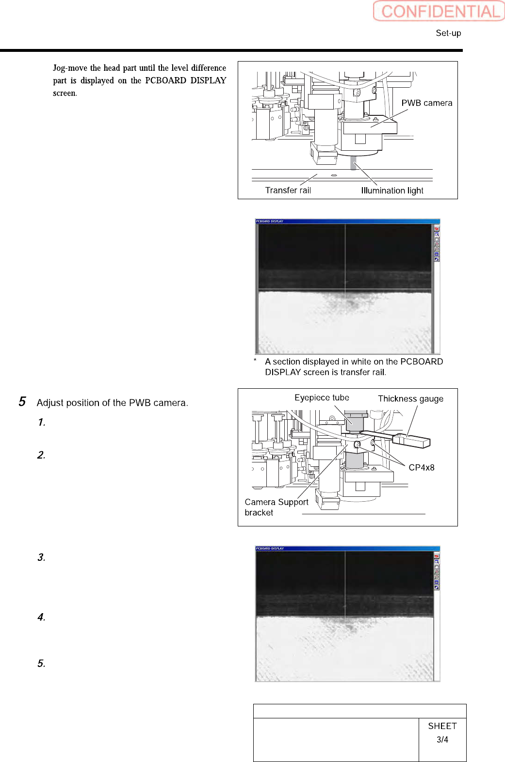
Loosen cap screws (2-CP4x8) fixing
the PWB camera.
Put thickness gauge of 1.0mm between
the PWB camera and the camera
support bracket and temporarily fix
them.
Adjust inclination of the transfer rail
displayed on the PCBOARD DISPLAY
screen so as to align it with the
cross-hair line.
After adjusting inclination, tighten the
cap screws (2-CP4x8) to fix the PWB
camera.
Remove the thickness gauge.
HLGB-10204-01
PWB Camera Setup
HLGB-10205-01
Fiducial Mark Setup
[Necessary jigs]
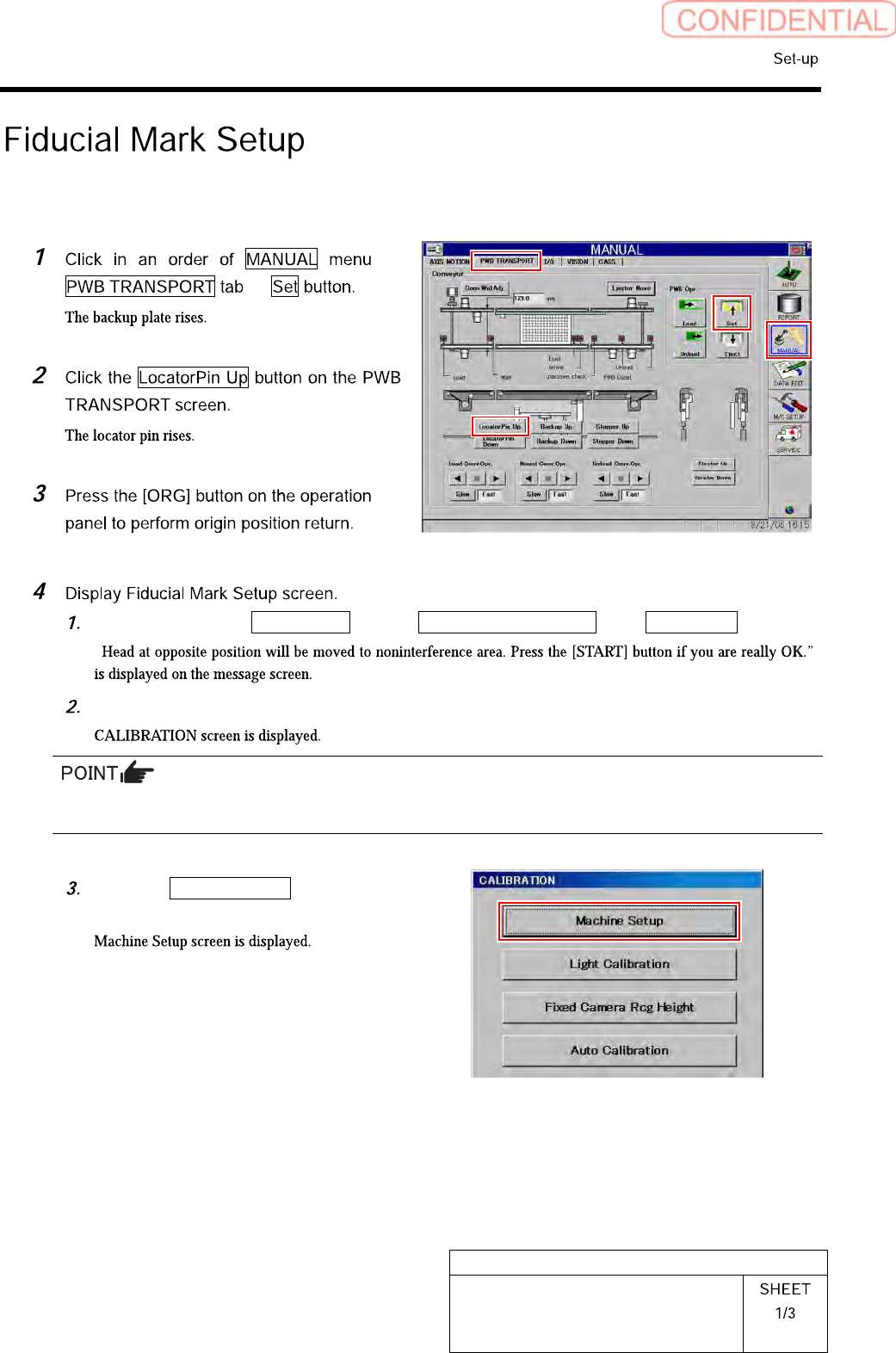
Click in an order of M/C SETUP menuM/C MAINTENANCE tabCalibration button.
“
Press the [START] button on the operation panel.
For procedures when selecting head for which calibration is performed, and when changing calibration jig,
refer to the “How to display calibration screen (HLGB-10105-01)”.
Click the Machine Setup button on the
CALIBRATION screen.