MAN00000772_SI-G200BB_SVCPDFA.pdf - 第344页
HLGB-10418-01 Adjustment of PWB St op per Sensor [Procedure] Any PWB sized to be mountable on this machine can be allowed. Mountable PWB: - Minimum PWB dimension: 50 x 50 mm - Max imum PWB d ime nsion: 460 x 360 mm - PWB…
HLGB-10417-01
Adjustment of Cassette Float Sensor
Height
Set the feed adjusting jig and cassette float sensor height adjusting jig on the position of
No.39 on the cassette table.
There should be no gap between the feed adjusting jig and the cassette table.
Adjust the height of the BS-63T attachment bracket in the same procedure as in the
procedure 7.
If the height is respectively adjusted at the positions of No.1, 20 and 39 on the cassette table, response
condition adjusted at the previous position varies. Be sure to check response of the sensor at the 3
locations after adjustment.
Remove the cassette float sensor adjusting jig and feed adjusting jig.
Remove the replacing carrier.
HLGB-10418-01
Adjustment of PWB Stopper Sensor
[Procedure]
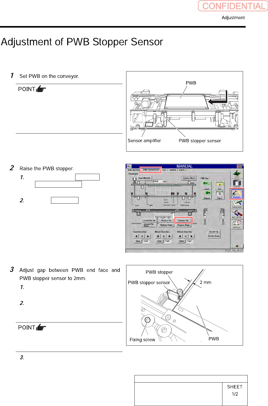
Any PWB sized to be mountable on this
machine can be allowed.
Mountable PWB:
- Minimum PWB dimension: 50 x 50 mm
- Maximum PWB dimension: 460 x 360 mm
- PWB thickness: 0.5 to 2.6 mm
Click in an order of MANUAL menu
PWB TRANSPORT tab to open the
PWB TRANSPORT screen.
Click the Stopper Up button to raise
the PWB stopper.
Loosen the fixing screws for PWB
stopper sensor.
Adjust the position of the sensor so
that the gap between the PWB and the
PWB stopper sensor.
The gap can be easily adjusted by inserting a
hexagon wrench of 2 mm between the PWB and
the PWB stopper.
Tighten the fixing screws for the PWB
stopper sensor.
HLGB-10418-01
Adjustment of PWB Stopper Sensor
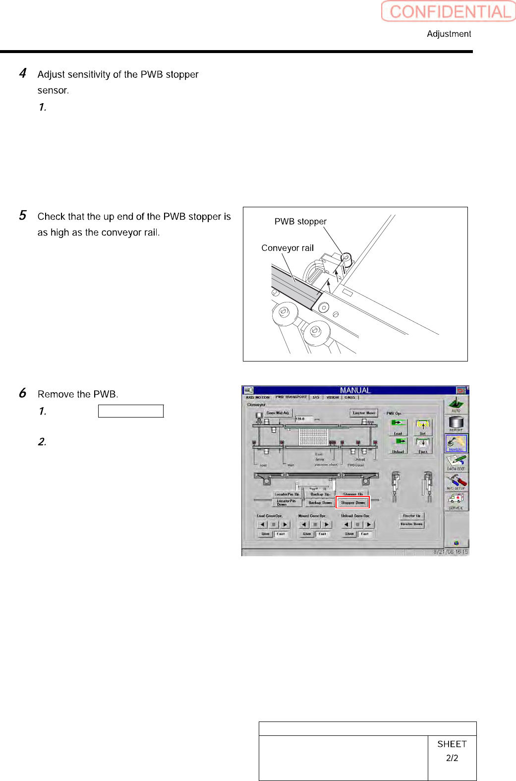
Make adjustment by turning the
sensitivity adjustment volume of the
sensor amplifier so that the PWB
stopper sensor is turned on (both of the
green LED and orange LED light up)
at this position.
Click the Stopper Down button to
lower the reference pin.
Remove the PWB on the conveyor.