MAN00000772_SI-G200BB_SVCPDFA.pdf - 第168页
HLGB-10201-01 RT Axis Origin Position Setup Perform this working on b o th he ads on t he front side and rear side. [Necessary jigs] • R T o r igin jig [Procedure] Click in an order of M/C SETUP menu M/C MAINTENANC…
HLGB-10106-01
Origin Return of the Unit (M/C ORG)
< Operating sequence of origin return >
Origin return of H/F axis
Origin return of X/Y axis, RT/RN axis
Turn OFF the interlock key when removing the alternation cart after origin return or when opening the
door to perform working.
Since the function of the area sensor is enabled when the interlock key is ON, the unit is in the emergency
stop state if your hand etc is put into the unit.
Similarly, when the alternation cart is removed from the unit with the interlock being ON, the unit is in
the emergency stop.
HLGB-10201-01
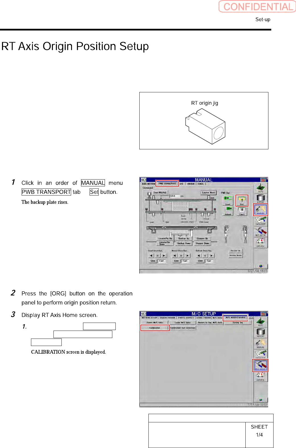
RT Axis Origin Position Setup
Perform this working on both heads on the front side and rear side.
[Necessary jigs]
• RT origin jig
[Procedure]
Click in an order of M/C SETUP
menu M/C MAINTENANCE tab
Calibration button.
HLGB-10201-01
RT Axis Origin Position Setup
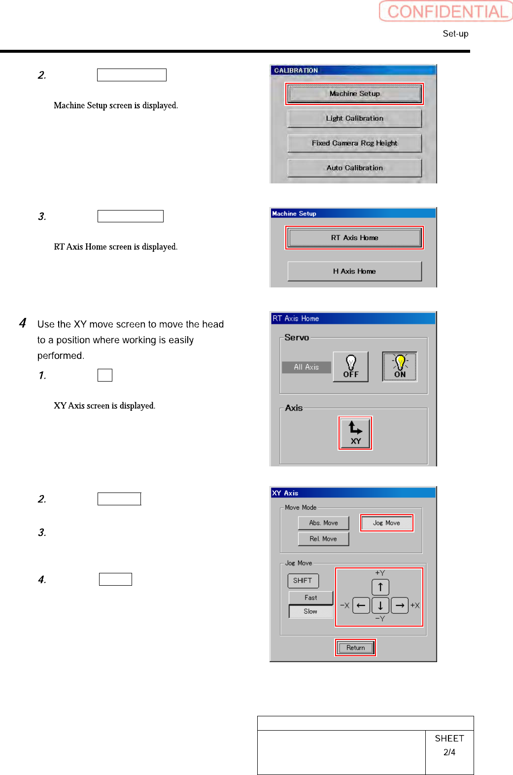
Click the Machine Setup button on the
CALIBRATION screen.
Click the RT Axis Home button on the
Machine Setup screen.
Click the XY button on the RT Axis
Home screen.
Click the Jog Move button in the move
mode.
Press the cursor key to move the head
to a position where working is easily
performed.
Press the Return button after the
head moves to close the XY axis
screen.