MAN00000772_SI-G200BB_SVCPDFA.pdf - 第45页
Install Tray Unit (Including machine modification) SHEET 6/73 WKGB-10104-03 Installing Tray Unit (Including machine modificat ion) [Checking prevention of interference(between F ax is motor and frame/connector and frame)…
Install Tray Unit (Including machine modification)
SHEET
5/73
WKGB-10104-03
Installing Tray Unit
(Including machine modification)
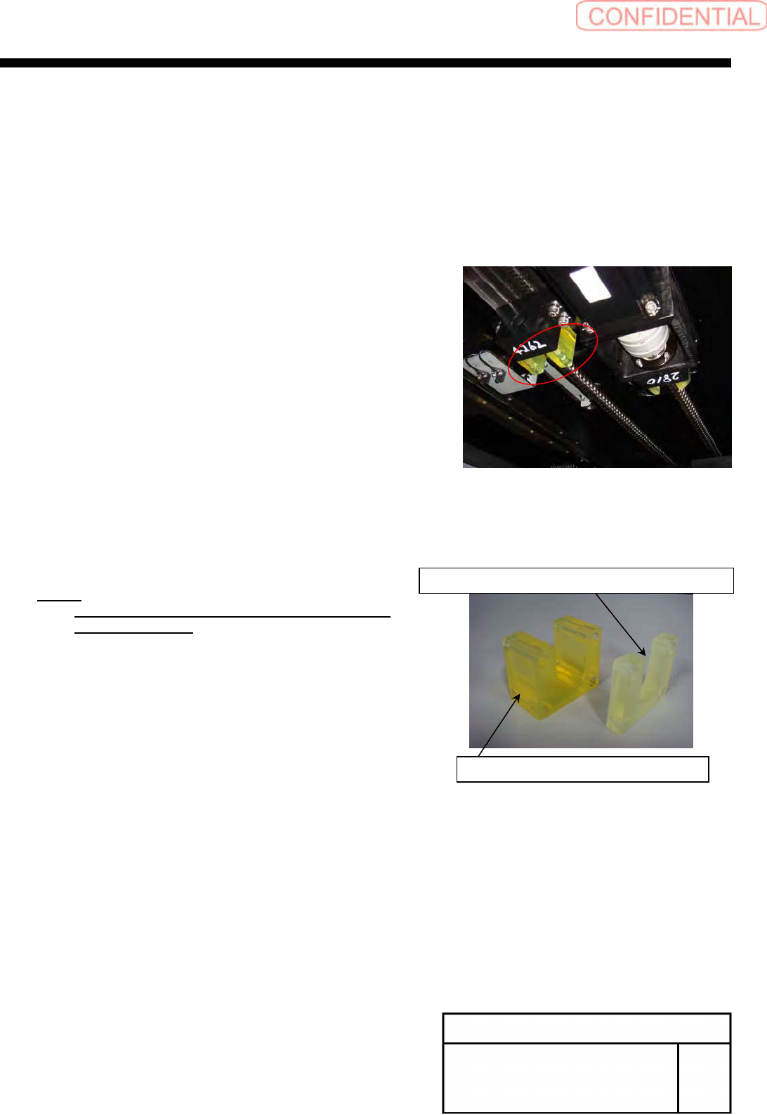
[Replacing Y axis urethane stopper (Rear head only)]
1
Turn off power for the unit.
2
Open the slide door on the rear side, and
move the rear head to the front wherever
possible.
3
Remove the bolts 4-CP4x30, and remove
the existing urethane stopper.
4
Apply small amount of LOCKTITE 242 to
the bolts 4-CP4x10 and install the
urethane stopper for tray specification.
NOTE:
Urethane stopper for replacement is only for
tray specification.
Existing urethane stopper (33[mm])
Urethane stopper for tray specification (11[mm])
Install Tray Unit (Including machine modification)
SHEET
6/73
WKGB-10104-03
Installing Tray Unit
(Including machine modification)
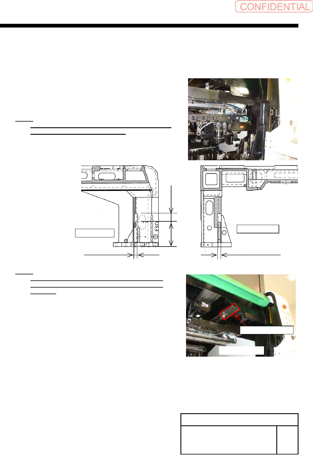
[Checking prevention of interference(between F axis motor and
frame/connector and frame)]
1
Move the rear head to the mechanical ends
in -X,+Y directions.
2
Check that the F axis motor does not
interfere with the frame support column.
NOTE:
If interference between the F axis motor and frame
has been checked, grind the frame.
NOTE:
Frames of KG0201 and later, NTG0100 and later,
NY0001 and later are interference prevention
products.
Serial marking location
Unit rear side
25[mm] 23[mm]
60[mm] 173[mm]
FrontSide
Frontview
Install Tray Unit (Including machine modification)
SHEET
7/73
WKGB-10104-03
Installing Tray Unit
(Including machine modification)
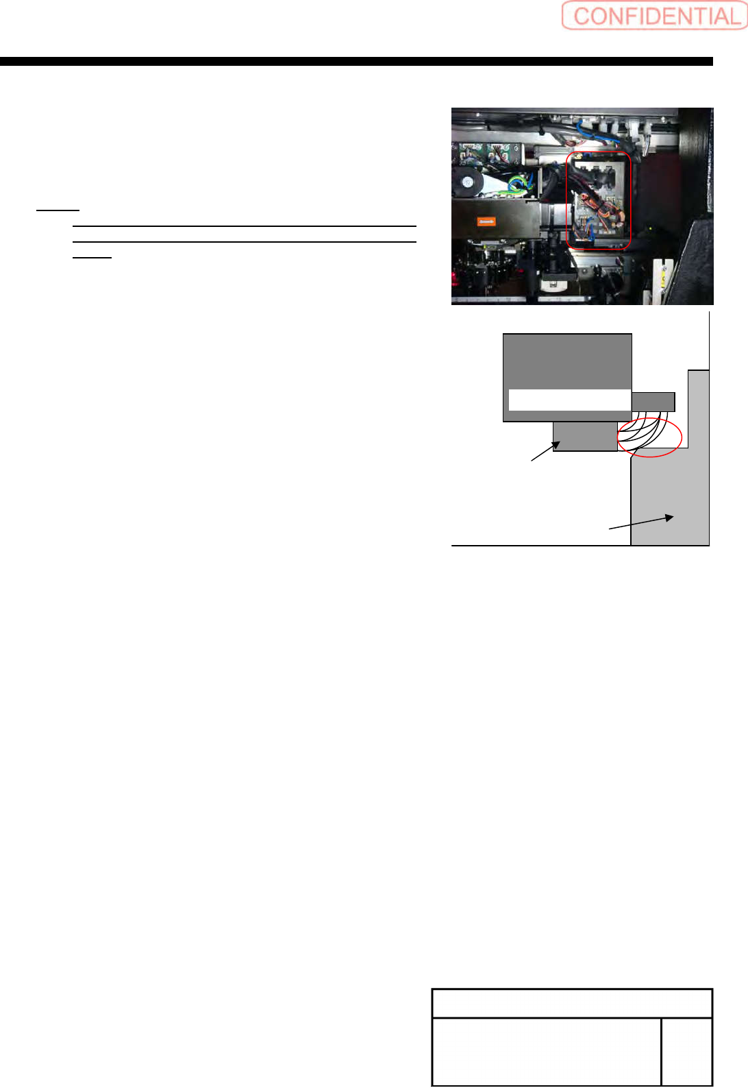
3
Confirm the cable doesn't touch to the pillar
of the frame, when head moved to
mechanical end position(-X direction and +Y
direction).
NOTE:
If the cable touch to pillar of frame, please change
the shape of cable wiring around the connector
panel.
Pillarofframe
RearHeadunit
RearF-axisunit
ThissideisRearsideofmounter