MAN00000772_SI-G200BB_SVCPDFA.pdf - 第683页
Chan ge Procedu re for RN axi s Ti min g Be l t [Reass e m b l y] 10 Apply the n ew tim ing belt to pulley o n the head side in t he rev erse orde r of the above proce dure. 11 Apply the R N timi ng belt to t he pulley o…
Change Procedure for RN-axis Timing Belt
8
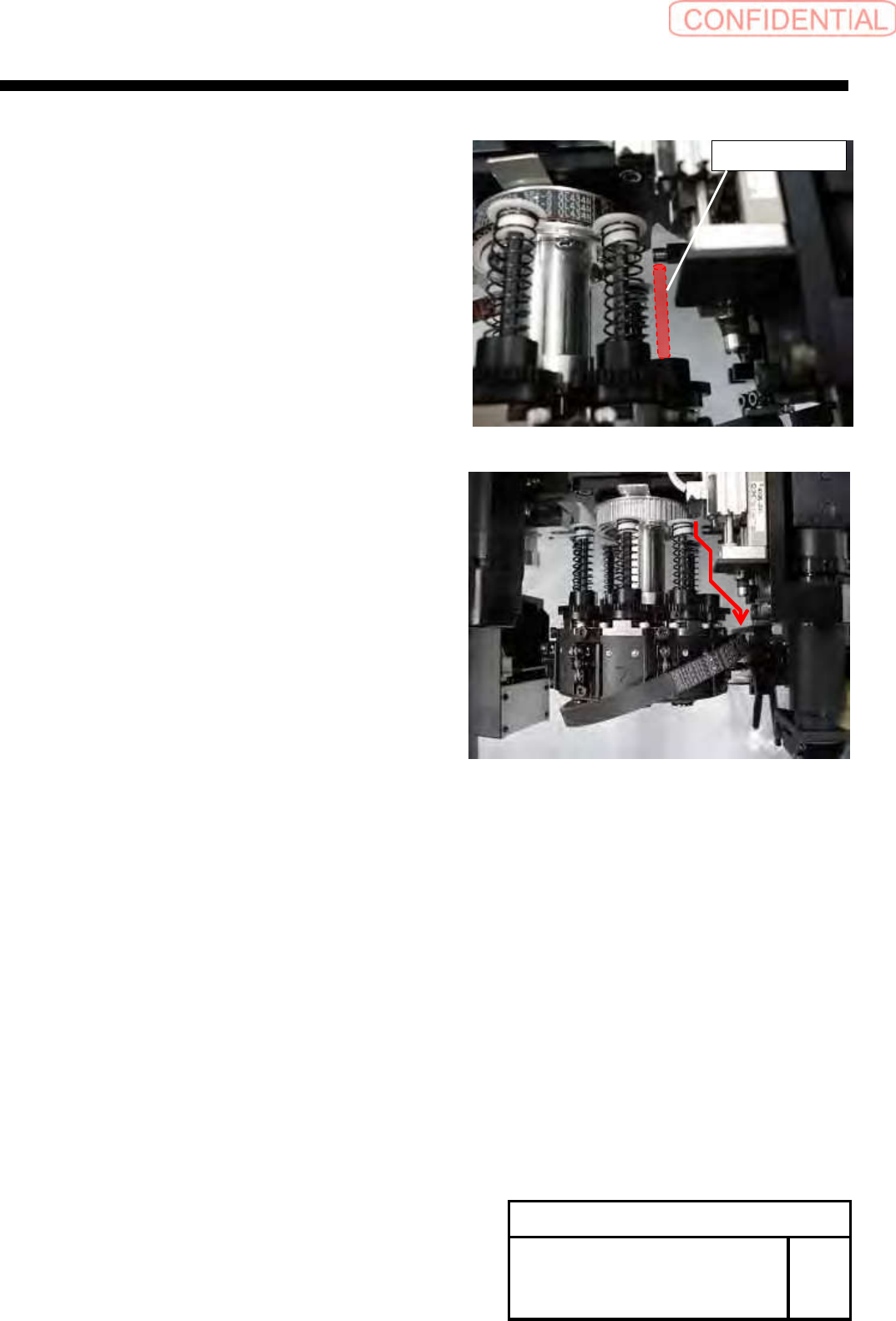
Remove the inner shaft, then move the position
to under the H axis lever.
9
Remove the timing belt through the gap between
H axis lever and plunger.
Change Procedure for RN-axis
Timing Belt
SHEET
2/3
RPGB-10801-1
Inner Shaft

Change Procedure for RN axis Timing Belt
[Reassembly]
10
Apply the new timing belt to pulley on the head
side in the reverse order of the above procedure.
11
Apply the RN timing belt to the pulley on the motor side.
1. Confirm the condition of item 2 again.
Temporarily attach the RN bracket.
12
Adjust the tension of RN timing belt, refer to RPGB-10501-1.
13
Attach the inner shaft. (Removed it item8)
[Adjustment]
14
Adjust the nozzle detection sensor position.
Refer to HLGB-10413-01.
15
Calibration
1. HLGB-10207-01 RN ORG Offset Setting
2. HLGB-10414-01 Nozzle Phase Adjustment
3. HLGB-10304-01 Calibration
Change Procedure for RN-axis
Timing Belt
SHEET
3/3
RPGB-10801-1
Change Procedure for RT Axis Timing Belt
Change Procedure for RT Axis Timing Belt
[Necessary Jigs]
Head block
Tension Meter (UNITTA U-507)
Belt Tension JIG
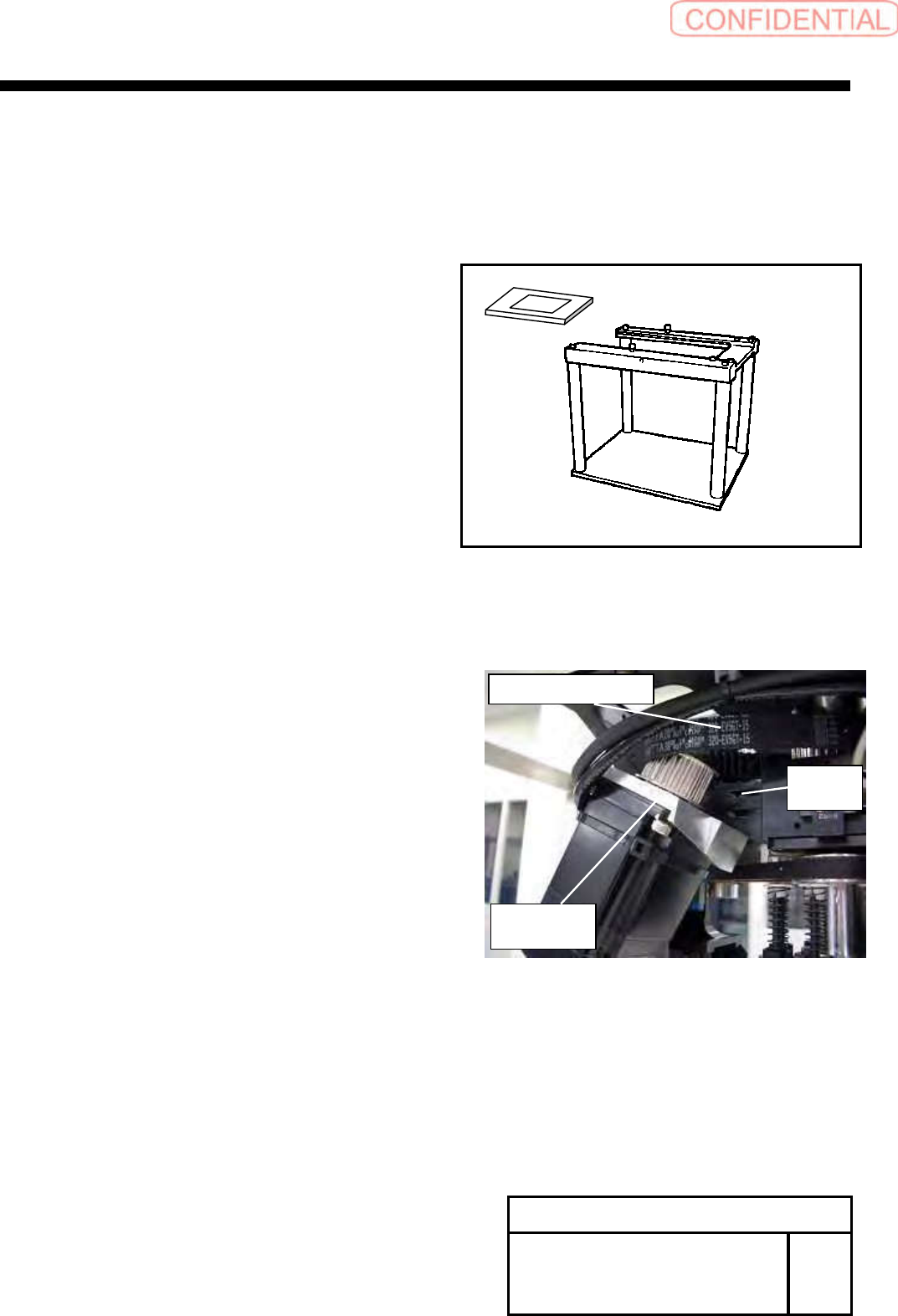
[Disassembly]
1
For the removal procedure for the head unit refer to
RPGB-10301-1
The following procedure is designed for the work on the
head block.
2
Remove the screws (2-C4x18), tilt the RT axis motor bracket.
Refer to RPGB-10601-1 _ 5
3
Remove the RT axis timing belt from the pulley on the motor side.
Change Procedure for RT-axis
Timing Belt
SHEET
1/3
RPGB-10901-1
RT Axis motor
bracket
C
4
x
18
W4
RT Axis timing belt