MAN00000772_SI-G200BB_SVCPDFA.pdf - 第332页
HLGB-10414-01 Phase A djustment for Nozzle Click the R.H b utton on the AXI S MOTION screen. Click the Abs. Move button on the RN/H-axis screen. Click the RN-Axis button and inpu t “120” into the input spa c e. Press the…
Adjustment
HLGB-10414-01
Phase Adjustment for Nozzle
SHEET
6/7
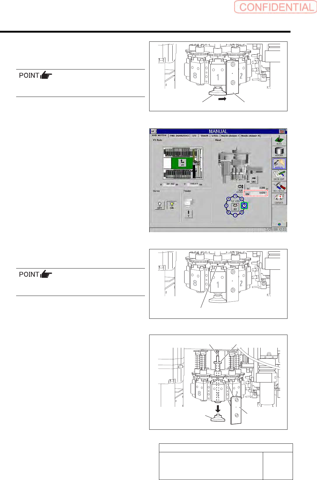
5.
Turn the inner shaft and the phase
adjusting jig (2) to lightly press them
against the phase adjusting jig (1).
Now check that the marking on the inner shaft
is directed toward you.
6.
Check that current position of the RN
axis is 0° on the axis operation screen.
7.
Tighten the sect screw (left) for the
small gear to 15[cN・m].
Check that the small gear is as high as the large
gear.
8.
Remove the phase adjusting jig (1) and
phase adjusting jig (2) from the head.
9.
Remove the inner shaft and the
pull-out jig from the head.
Phase adjusting jig (2)
Phase adjusting jig (1)
Set screw (Left)
Phase adjusting
jig (2)
Phase adjusting
jig (1)
Pull-out jig Inner shaft
HLGB-10414-01
Phase Adjustment for Nozzle
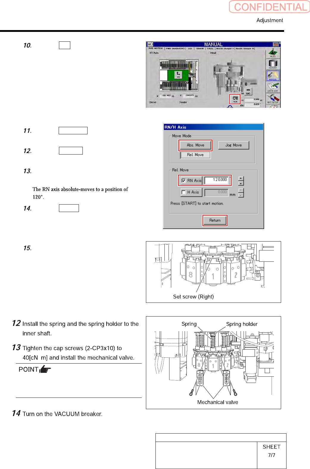
Click the R.H button on the AXIS
MOTION screen.
Click the Abs. Move button on the
RN/H-axis screen.
Click the RN-Axis button and input
“120” into the input space.
Press the [START] button on the
operation panel.
Click the Return button to close the
RN/H axis screen.
Tighten the sect screw (right) for the
small gear to 15[cN・m].
・
Tighten 2-CP3x10 for fixing mechanical valve on
the upper and lower sides alternately little by
little.
HLGB-10415-01
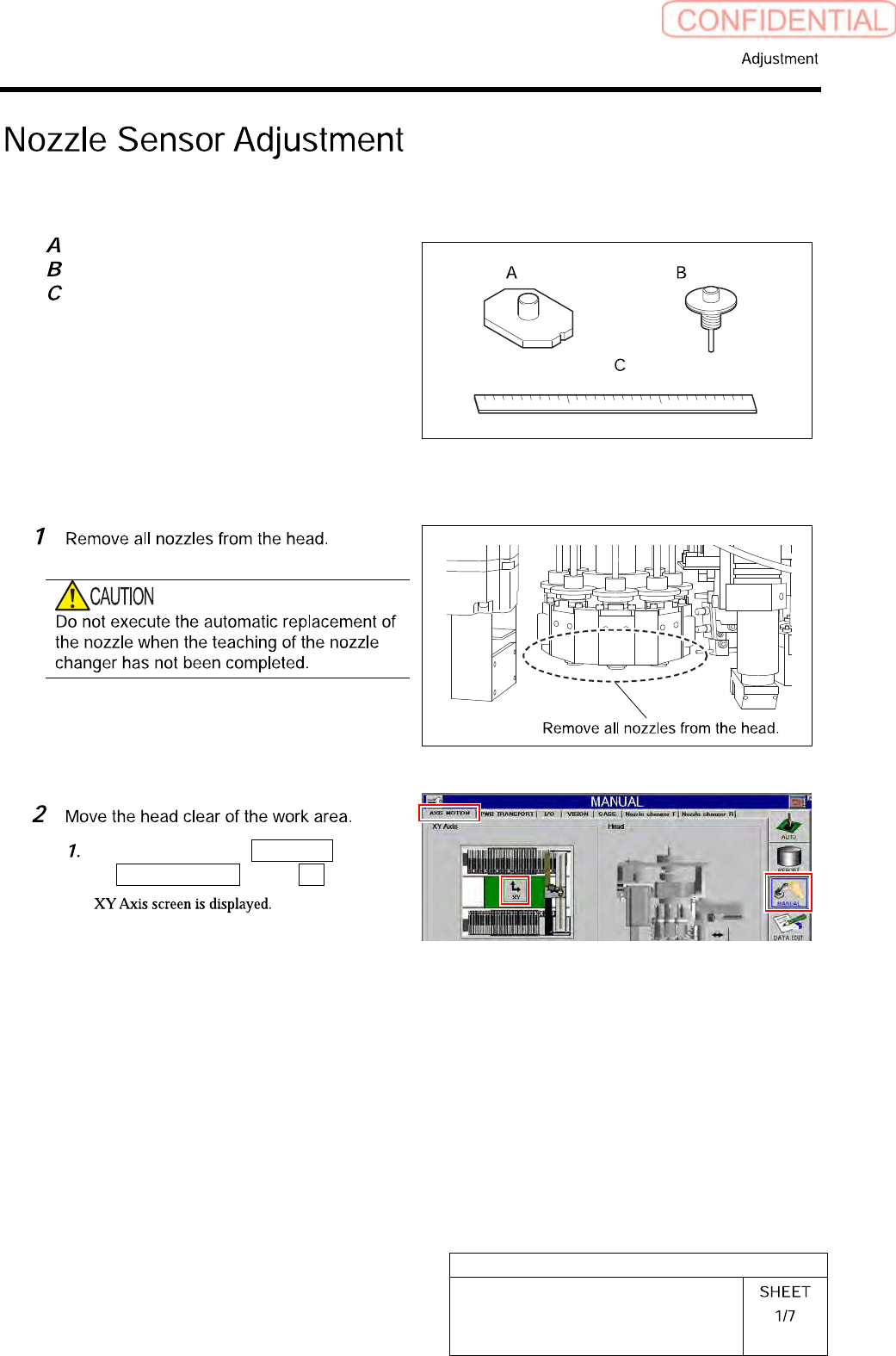
Nozzle Sensor Adjustment
[Necessary jigs]
Jig nozzle for nozzle changer
Nozzle (used in production)
Scale (about 300 mm)
[Adjust the sensor attachment height]
Click in an order of MANUAL menu
AXIS MOTION tab XY button.